


When I look at a single-line diagram, I usually start with familiar things.
Where does the power come from?
How is it distributed?
What is the transformer capacity?
Which breaker protects which feeder?
But there is another question worth asking.
What happens if this one component fails?
That simple question can change the way we read a single-line diagram.
Follow the Power Path

Consider a simple critical power system:
Source → Switchgear → Transformer → UPS → Distribution Board → Critical Load
Everything may look perfectly normal.
Each piece of equipment may have enough capacity.
Protection may be properly coordinated.
But now imagine one component at a time becoming unavailable.
What if the transformer fails?

What if the UPS output breaker cannot close?
What if one common distribution board is lost?
Does another power path exist?
Or does the entire critical load disappear with that one failure?
This is where the concept of a SPOF (Single Point of Failure) becomes useful.
A SPOF is simply a component or point whose failure can cause the required system function to be lost.
Redundant Equipment Does Not Always Mean a Redundant System
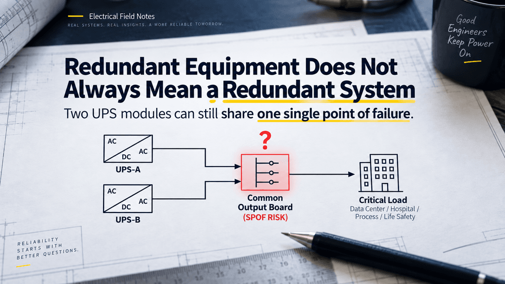
This is an easy trap.
Imagine two UPS modules.
At first glance, the system looks redundant.
But both UPS units feed one common output switchboard.
If that switchboard fails, both UPS modules become irrelevant to the load.
So the question is not only:
“Do we have backup equipment?”
It is:
“Do we have another complete path to the load?”
That difference matters.
UPS redundancy can exist at the equipment level while a SPOF still remains somewhere else in the electrical path.
Read the Diagram From the Load Backward

One simple way to review this is to start at the critical load and trace the power path backward.
Ask at each point:
If I lose this component, can the load still be energized?
For example:
Critical Load
← Distribution Board
← UPS
← Transformer
← Switchgear
← Source
Then look for alternate paths.
If there is only one possible path through a particular component, that point deserves attention.
It does not automatically mean the design is wrong.
Not every facility requires full redundancy.
The required level of resilience depends on the importance of the load, project philosophy, cost, and operational requirements.
But it should at least be a conscious design decision.
The Diagram Tells More Than Capacity
A single-line diagram is not just a drawing of electrical equipment.
It also shows dependency.
Which equipment depends on what?
Where do two supposedly independent paths become common?
Where could one failure affect multiple downstream systems?
Once I started looking at diagrams this way, redundancy became easier to understand.
Instead of memorizing terms such as N+1, 2N, or fault tolerance, I can start with a simpler question:
“What happens if this line disappears?”
That question naturally leads to the bigger concepts.
Field Checklist
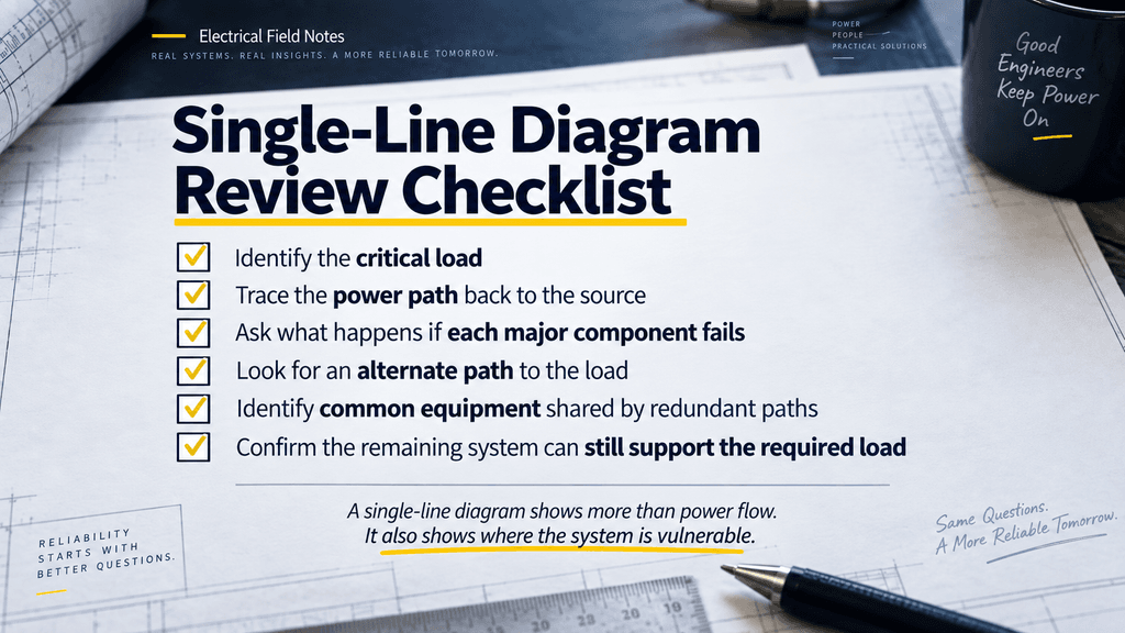
When reviewing a single-line diagram:
□ Identify the critical load
□ Trace its power path back to the source
□ Ask what happens if each major component fails
□ Look for an alternate path to the load
□ Identify common equipment shared by redundant paths
□ Check whether one failure can remove multiple supposedly independent sources
□ Confirm whether the remaining system can still support the required load
A single-line diagram tells us how power flows.
But if we look a little closer, it can also tell us where the system is vulnerable.
Sometimes finding a SPOF starts with nothing more than asking:
“What happens if this one component is lost?”
Safety Note:
Actual redundancy, switching capability, and failure response should be verified against the approved design, operating philosophy, equipment ratings, protection scheme, and manufacturer requirements. Switching or testing energized electrical systems should only be performed by authorized personnel following approved safety procedures.