
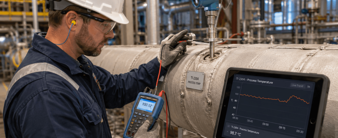
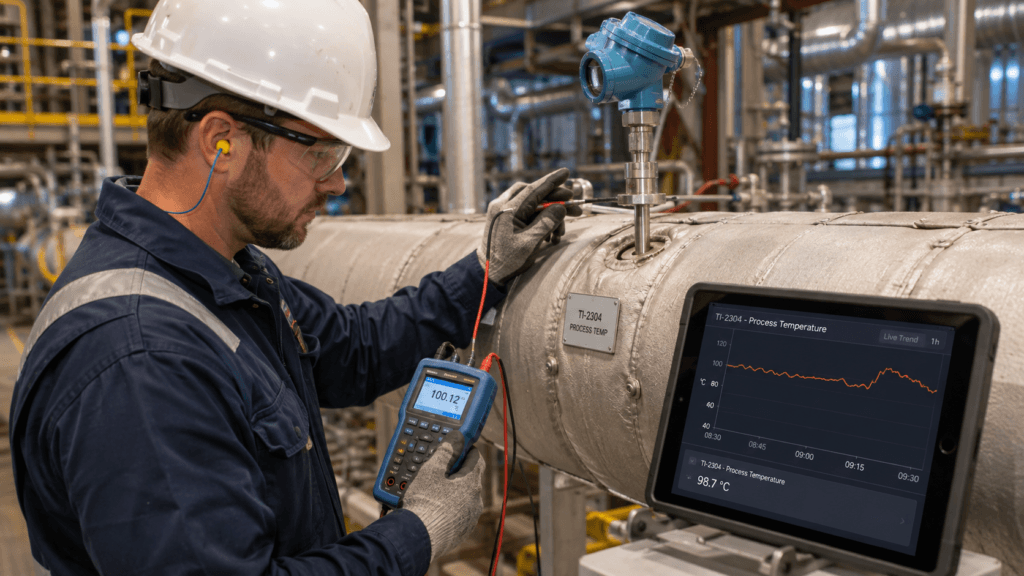
The temperature reading looked wrong.
So we checked the sensor.
The RTD was removed, tested, and compared with a reference.
It was accurate.
The transmitter was also fine.
But after reinstalling everything, the process temperature still did not make sense.
That is when the question changed.
Was the sensor measuring temperature incorrectly?
Or was it accurately measuring the temperature at the wrong place?
A calibrated sensor does not guarantee an accurate process measurement.
Calibration Checks the Sensor, Not the Installation
A temperature sensor can perform perfectly in a calibration bath or dry-block calibrator.
But once installed in a pipe or vessel, the measurement depends on much more than sensor accuracy.
The complete measurement chain looks more like this:
Process Temperature → Heat Transfer → Thermowell → Sensor → Transmitter → Control System
If the temperature reaching the sensing element does not represent the actual process, perfect calibration will not fix the measurement.
1. Check the Thermowell Insertion Depth
This is one of the first things worth checking.
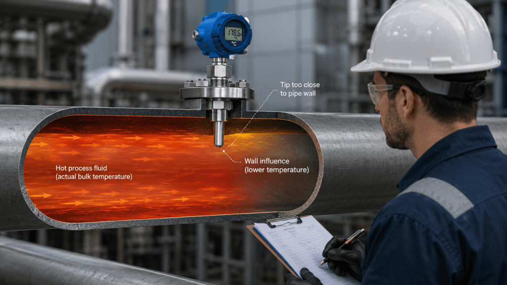
If the thermowell does not extend far enough into the process, the sensor may be influenced by the pipe wall instead of the flowing fluid.
For example:
- Process fluid: 150°C
- Pipe wall: significantly cooler
- Sensor tip: installed too close to the wall
The RTD may accurately report the temperature around its tip.
The problem is that the tip is not seeing a representative process temperature.
Do not assume the installation is correct simply because the thermowell fits the nozzle.
Check the actual insertion depth against the pipe size and process conditions.
2. Look for Heat Conduction Through the Installation
Heat does not travel only from the process into the sensor.
It can also travel through the thermowell, connection, and surrounding metal.
This becomes more significant when:
- The thermowell has shallow insertion
- The process flow is low
- The temperature difference between process and ambient is large
- The connection has a large metal mass
- The surrounding piping is poorly insulated
The result can be a stable but biased temperature reading.
Nothing appears electrically wrong.
The measurement simply settles at the wrong thermal balance.
3. Make Sure the Sensor Is Properly Seated
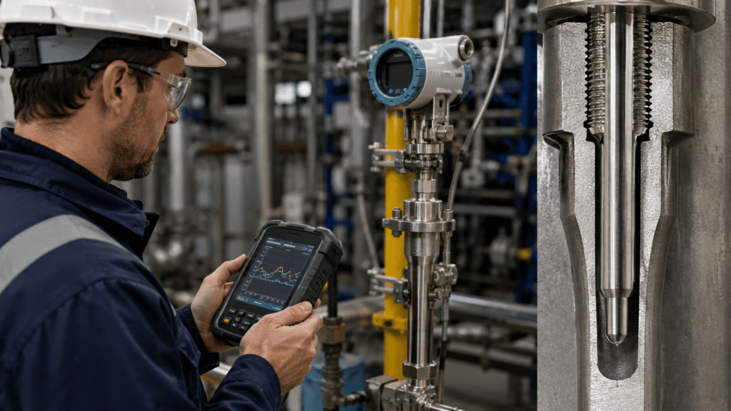
The sensing element should have good thermal contact with the bottom of the thermowell.
Problems can occur when:
- The sensor is too short
- The spring-loaded insert is damaged
- The sensing element does not reach the thermowell tip
- Debris prevents full insertion
- The wrong replacement sensor length was installed
A small air gap can significantly slow heat transfer.
The reading may eventually approach the process temperature, but the response becomes much slower.
This often appears as:
“The temperature sensor is lagging.”
The sensor itself may be perfectly healthy.
4. Check Where the Temperature Is Being Measured
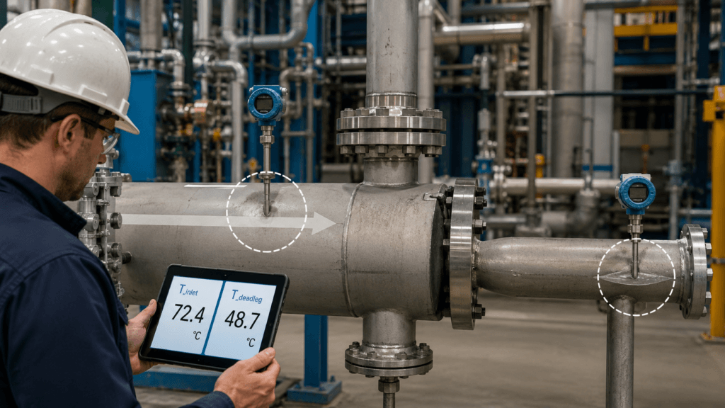
Location matters as much as sensor accuracy.
A sensor installed near:
- A cold feed inlet
- A steam injection point
- A heat exchanger outlet
- A vessel wall
- A bypass connection
- A stagnant branch
- A mixing point
may measure a very different temperature from another point only a short distance away.
This becomes especially important when someone compares two instruments and asks:
“Why are these two temperatures different?”
Before adjusting calibration, ask:
Are they actually measuring the same process condition?
Sometimes the correct answer is no.
5. Check the Flow Around the Thermowell
Temperature measurement depends on heat transfer.
Low or stagnant flow can reduce that heat transfer dramatically.
A sensor installed in a dead leg or low-flow branch may respond slowly and can be heavily influenced by ambient temperature.
Possible causes include:
- Closed or partially closed valve
- Blocked branch
- Low process flow
- Incorrect sensor location
- Poor mixing
- Product buildup around the thermowell
A sensor cannot measure the main process temperature if the process is barely reaching the sensing point.
6. Compare the Dynamic Response, Not Just the Number
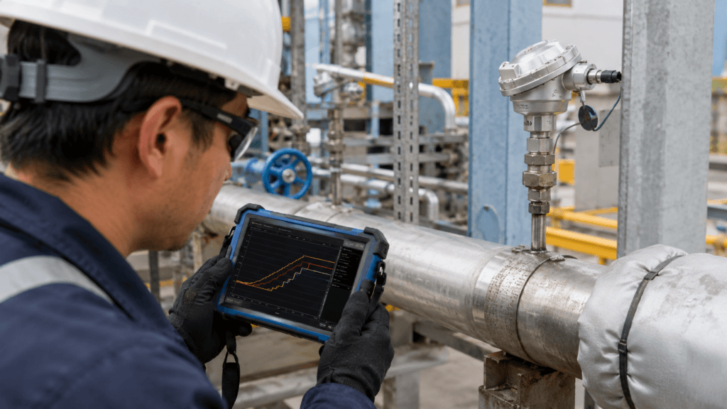
A useful clue is how the temperature changes when the process changes.
Suppose the process heats rapidly.
One sensor responds immediately.
Another takes several minutes.
Both eventually show similar values.
The problem may not be calibration.
It may be:
- Poor thermal contact
- Excessive thermowell mass
- Low local flow
- Deposits on the thermowell
- Incorrect insertion depth
Trend data can reveal these problems better than a single temperature reading.
Look at response shape and response time, not only the final value.
7. Do Not Forget the Thermowell Surface
The process side of the thermowell can also change over time.
Deposits, scale, polymer, corrosion products, or other buildup can act as thermal insulation.
The sensor remains accurate.
The transmitter remains accurate.
But heat now takes longer to reach the sensing element.
If temperature response gradually becomes slower over months or years, inspect the process side as well as the electrical side.
A Practical Troubleshooting Sequence
When a temperature reading looks wrong but the sensor passes calibration, I would move through the problem like this.
Step 1 — Confirm the Measurement Chain
- Sensor calibration
- Transmitter configuration
- RTD or thermocouple type
- Wiring
- Scaling in PLC or DCS
If these are correct, stop repeatedly checking the same electrical loop.
Move to the installation.
Step 2 — Check the Sensor and Thermowell
- Correct sensor length
- Sensor fully seated
- Spring loading
- Thermowell condition
- Insertion depth
Step 3 — Check the Process Location
- Is there enough flow?
- Is the point representative?
- Is it near a mixing zone?
- Could the pipe or vessel wall influence the reading?
- Is it installed in a dead leg?
Step 4 — Compare the Trend
Do not compare only:
Sensor A = 147°C
Sensor B = 151°C
Compare what happens during an actual process change.
Which one responds first?
Which one lags?
Does the difference increase at low flow?
Does the error become larger as process temperature rises?
Those patterns often tell more than another calibration check.
Field Checklist
If the sensor is accurate but the process temperature still looks wrong, check:
- Is the correct sensor type configured?
- Is the sensing element fully seated in the thermowell?
- Is the sensor the correct length?
- Is the thermowell inserted far enough into the process?
- Could pipe-wall conduction influence the measurement?
- Is there sufficient flow around the thermowell?
- Is the measurement point representative of the process?
- Is the sensor located near a mixing point, inlet, or dead leg?
- Is there buildup on the thermowell?
- Does the trend show abnormal response time or lag?
Final Thought
Calibration answers an important question:
“Is the sensor accurate?”
But process troubleshooting requires another question:
“Is the sensor accurately measuring what I actually want to know?”
Those are not the same thing.
When a calibrated temperature sensor still gives an unbelievable reading, do not immediately recalibrate it again.
Look at the installation.
Look at the thermowell.
Look at the flow.
And most importantly, look at what temperature the sensor is actually exposed to.
Safety Notice
Temperature instruments may be installed on hot, pressurized, corrosive, toxic, or otherwise hazardous process systems.
Inspection, removal, or replacement of sensors and thermowells should only be performed by qualified personnel under approved procedures.
Before removing process-mounted instrumentation:
- Confirm process pressure and temperature
- Isolate the equipment where required
- Depressurize and drain the connection according to procedure
- Apply lockout/tagout where applicable
- Use the required PPE
- Never remove a thermowell or process connection from a pressurized system unless the installation is specifically designed and approved for that procedure