
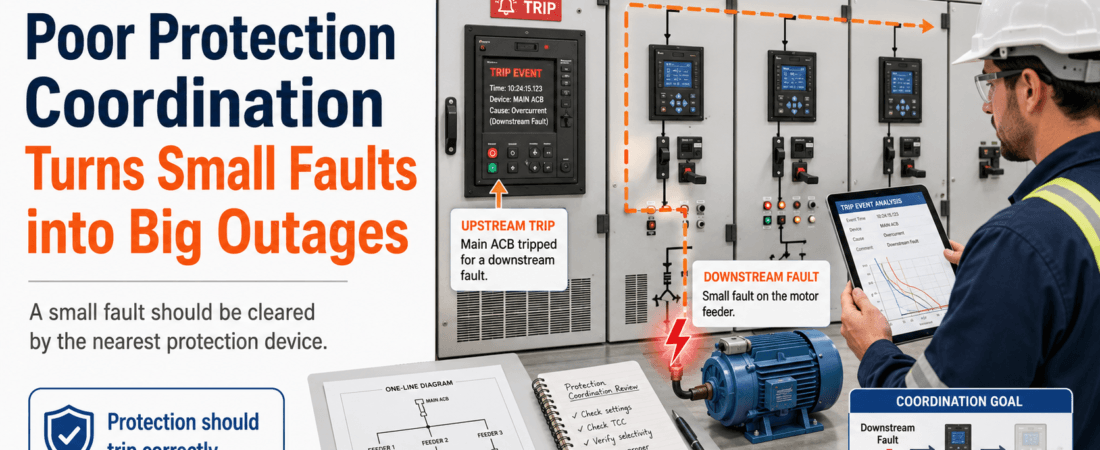
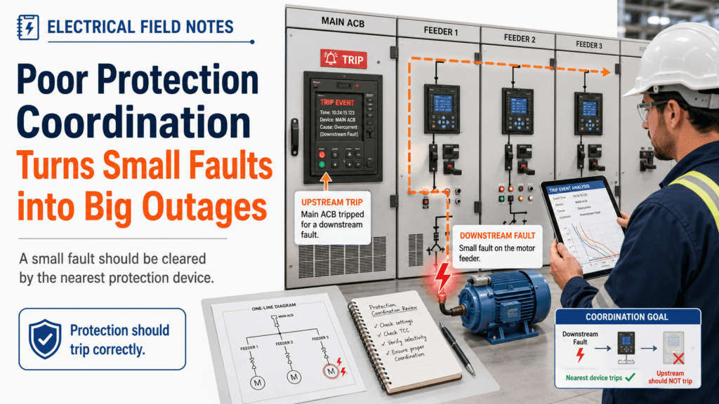
A small fault should not become a big outage.
This is one of the basic ideas of electrical protection.
If a small motor has a fault, the local protection should clear it.
If one feeder has a problem, the feeder breaker should trip.
If one panel has an issue, the upstream main breaker should not be the first device to operate.
In theory, this sounds obvious.
But in the field, this is where many painful shutdowns begin.
A local fault happens.
The nearest protection device does not clear it properly.
Then the upstream breaker trips.
Suddenly, one small equipment problem becomes a much larger production loss.
That is not just a breaker problem.
It is a protection coordination problem.
A Small Fault Should Be Cleared Locally
The purpose of protection is not only to trip during a fault.
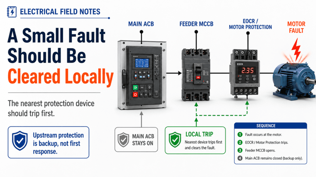
The real purpose is to trip the right device at the right time.
This is called selectivity or coordination.
The closest protection device to the fault should operate first. Upstream devices should act as backup, not as the first response for every small fault.
For example, if a small motor has an overload or ground fault, the motor protection device should clear it before the main ACB trips.
If the main breaker trips first, the damage is no longer local.
Now the issue affects other healthy loads, production equipment, control systems, lighting, utilities, and sometimes even safety-related systems.
The electrical fault may be small.
But the operational impact becomes large.
The Main Breaker Is Not Always the Root Cause
When a main ACB trips, people often focus on the main breaker.
“Why did the main ACB trip?”
“Is the ACB defective?”
“Is the setting too sensitive?”
“Should we increase the setting?”
These are understandable questions.
But the main breaker is often only the final device that reacted.
The real question should be:
Why did the downstream protection fail to isolate the fault first?
The cause may be a local overload relay that was not set correctly.
It may be an MCCB setting that does not coordinate with the upstream ACB.
It may be a ground fault setting mismatch.
It may be an instantaneous trip setting that overlaps with downstream protection.
It may be temporary equipment added without checking the protection study.
It may be a maintenance change that was never updated in the drawings or settings.
The breaker that trips is not always the breaker that caused the problem.
It is only showing where the protection chain finally acted.
Coordination Is a System, Not a Setting
Protection coordination is not just one relay setting.
It is a system relationship.
A typical low-voltage power system may include:
- Main ACB
- Feeder MCCB
- Motor protection relay or EOCR
- Local contactor and overload
- Ground fault relay
- Fuses
- VFD or soft starter protection
- UPS or emergency power source
- PLC or trip logic
- Cable size and fault current level
- Transformer capacity and impedance
Each protection device has its own operating characteristic.
Some act very fast.
Some act with time delay.
Some respond to overload.
Some respond to short circuit.
Some respond to ground fault.
Some are electronic.
Some are thermal-magnetic.
Some are built into equipment.
If these devices are not coordinated, the protection system can behave in unexpected ways.
A small downstream fault can trip an upstream breaker.
A local motor failure can stop an entire MCC section.
A minor ground fault can shut down healthy loads.
This is why protection coordination should be reviewed as a system, not as isolated settings.
Why Small Faults Become Big Outages
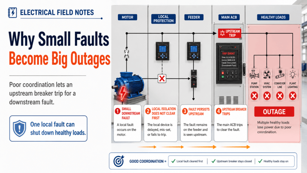
In the field, small faults often become big outages for several reasons.
One common reason is that local protection is not set properly.
For example, an overload relay may be left at a default value.
A motor protection relay may not match the motor full-load current.
A ground fault protection function may be disabled or set too high.
A feeder breaker may have an instantaneous setting that does not allow downstream protection enough time to operate.
Another reason is that the system has changed over time.
A new motor is added.
A VFD is installed.
A cable is replaced.
A feeder is modified.
A temporary load becomes permanent.
A spare feeder is reused for a different purpose.
But the protection settings are not reviewed.
The electrical system changes physically, but the protection philosophy remains frozen in the past.
That gap creates risk.
The Dangerous Habit: “Just Raise the Setting”
After an unwanted trip, one common reaction is to raise the upstream breaker setting.
This can feel practical.
The plant does not want another shutdown.
The main breaker tripped once.
So someone may think, “Let’s make it less sensitive.”
But this can be dangerous.
If the root cause is poor downstream protection, raising the upstream setting may only hide the problem.
The next fault may last longer.
Cable damage may increase.
Equipment damage may become worse.
Arc flash energy may increase.
The fault may not clear as intended.
A nuisance trip is frustrating.
But a protection device that does not trip when needed is much worse.
The goal is not to make the system trip less.
The goal is to make the correct device trip.
Check the Nearest Protection First
When a main breaker trips due to a downstream fault, I prefer to start from the local protection.
Was the motor protection relay set correctly?
Was the EOCR configured for the actual motor current?
Was ground fault protection available at the local level?
Was the feeder breaker setting correct?
Was the instantaneous function coordinated?
Was there a recent change in load, cable, motor, or control logic?
Did the downstream device receive the fault current long enough to operate?
Was the local protection bypassed, disabled, or incorrectly wired?
These questions are more useful than immediately blaming the main breaker.
The main breaker may have operated exactly as designed.
The problem may be that the protection layers below it were not doing their job.
Drawings and Settings Must Match the Field
Protection coordination depends on accurate data.
But in real plants, drawings and field conditions often drift apart.
A drawing may show the original motor size.
The field may have a different motor.
The protection study may assume one cable size.
The actual installation may be modified.
A breaker may be replaced with a different model.
A relay setting may be changed during maintenance.
A spare feeder may be reused without updating the single-line diagram.
When troubleshooting a protection issue, the drawing is only the starting point.
The field must be verified.
Check the actual breaker type.
Check the actual relay setting.
Check the motor nameplate.
Check the cable size.
Check the transformer source.
Check the grounding system.
Check recent modification history.
A protection study based on outdated information can give a false sense of security.
Protection Coordination Is Also a Business Issue
This is not only an electrical engineering topic.
It is a production risk topic.
When protection coordination is poor, one small failure can shut down multiple healthy systems. That means more downtime, more investigation time, more restart risk, and more pressure on the maintenance team.
A local motor fault may only require motor isolation and repair.
But if the main ACB trips, the site may need to restart several systems, confirm process conditions, reset alarms, inspect affected equipment, and recover production safely.
The cost of poor coordination is not only electrical damage.
It is lost time, lost production, and lost confidence in the power system.
A Practical Field Review Sequence
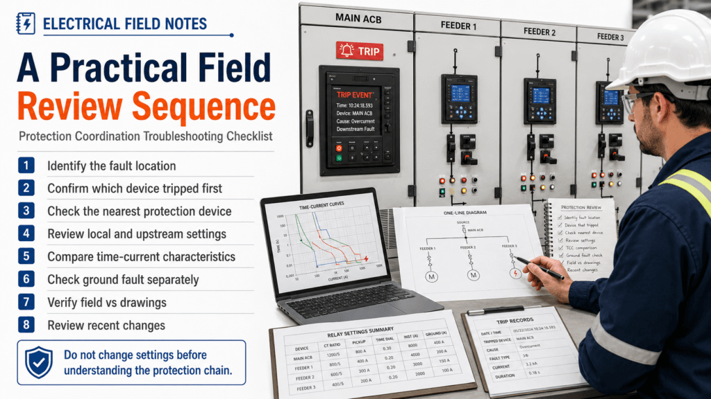
When reviewing this type of problem, I like to follow a simple sequence.
First, identify the actual fault location.
Second, confirm which protection device operated first.
Third, check whether the nearest downstream device should have operated.
Fourth, review the settings of local protection, feeder protection, and upstream protection.
Fifth, compare the time-current characteristics where possible.
Sixth, check ground fault protection separately from overload and short-circuit protection.
Seventh, verify the field installation against drawings and previous study data.
Eighth, review recent maintenance, equipment replacement, or load changes.
Finally, decide whether settings, wiring, device selection, or system design need to be corrected.
This approach is not about making every investigation complicated.
It is about avoiding a dangerous shortcut:
Changing settings before understanding the protection chain.
Final Thought
A small fault should be cleared by the nearest protection device.
If the main breaker trips first, the question is not only:
“Why did the main breaker trip?”
The better question is:
“Why did the downstream protection fail to isolate the fault?”
Poor protection coordination can turn a small motor fault into a plant-wide outage.
That is why protection should be reviewed as a system:
Local protection.
Feeder protection.
Main protection.
Ground fault protection.
Actual field installation.
Recent changes.
Updated drawings and settings.
Because in the field, the safest electrical system is not the one that never trips.
It is the one that trips correctly.