


A transmitter alarm does not always mean the transmitter is bad.
This sounds simple, but in the field, it is easy to forget.
When a pressure transmitter, level transmitter, flow transmitter, or temperature transmitter shows an abnormal value, the first reaction is often very fast.
“The transmitter is faulty.”
“Replace it.”
“Install a spare.”
“Calibrate it again.”
Sometimes that is correct.
But not always.
A transmitter is only one part of a complete measurement loop. The real problem may be in the process connection, impulse line, power supply, junction box, cable, shield grounding, signal isolator, analog input card, PLC/DCS scaling, or even recent maintenance work.
The signal is a clue, not the conclusion.
The Fastest Answer Is Not Always the Safest Answer
In a running plant, time pressure is real.
Operators want the alarm cleared.
Maintenance wants to restore normal operation.
Production wants the line back.
Managers want a clear answer.
So replacing the transmitter can feel like the fastest solution.
But there is a risk.
If the transmitter is not the root cause, replacement only resets the situation temporarily. The same alarm may come back. Or worse, the new transmitter may show the same abnormal value, and the team loses time while the process remains unstable.
That is why I prefer a simple rule:
Before replacing the transmitter, check the loop.
Not because transmitters never fail.
They do fail.
But because a 4–20 mA signal is a system, not a single device.
What the Measurement Loop Really Includes
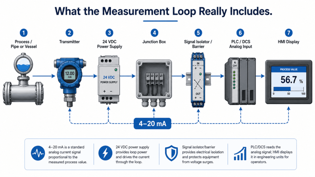
When we say “transmitter problem,” we may actually be talking about many different parts.
A typical measurement loop may include:
- Process tap or sensing point
- Root valve, manifold, impulse line, or tubing
- Transmitter body and sensor
- Local power supply
- Junction box
- Field cable
- Shield and grounding
- Signal isolator or barrier
- PLC/DCS analog input module
- Engineering unit scaling
- Alarm setting and logic
- HMI display
Any one of these can make a good transmitter look bad.
This is especially important for field instruments connected to PLC or DCS systems. The value shown on the screen is not just a raw field value. It is already processed, scaled, filtered, and displayed through several layers.
So when the displayed value looks wrong, the question should not be:
“Is the transmitter bad?”
The better question is:
“Where does the signal become wrong?”
Start from the Process Side
Before touching the transmitter electrically, I like to ask one basic question.
Is the process condition real?
For example, if a pressure transmitter reads low, the first possibility is not always an electrical fault. The pressure may actually be low.
The process line may be blocked.
A valve may be partially closed.
An impulse line may be clogged.
Condensate may be trapped.
Air may be trapped in the sensing line.
A manifold valve may be in the wrong position.
For differential pressure transmitters, this becomes even more important.
A small problem in the high-pressure or low-pressure side impulse line can create a completely wrong reading. The transmitter may be doing exactly what it is supposed to do, but the pressure reaching the transmitter is no longer representative of the process.
In that case, replacing the transmitter does not solve the problem.
The new transmitter will read the same wrong condition.
Check the Power Supply
A 2-wire transmitter depends on loop power.
If the power supply is unstable, low, noisy, or interrupted, the signal can become abnormal.
Before replacing the transmitter, check the supply voltage at the right point. Not only inside the control panel, but also at the field side when possible.
There can be voltage drop across long cable runs.
There can be loose terminals in a junction box.
There can be corrosion in field terminals.
There can be a bad fuse, bad isolator, or unstable power source.
A transmitter may look faulty simply because it is not receiving healthy power.
This is one of the reasons why checking only from the control room can be misleading. The panel side may look normal, but the field side may tell a different story.
Check the 4–20 mA Signal
For analog transmitters, the 4–20 mA signal gives useful clues.
A very low signal may indicate open circuit, no power, or transmitter failure.
A very high signal may indicate overrange, fault output, or wiring issue.
A signal stuck at one value may suggest process blockage, frozen signal, configuration issue, or input card problem.
A fluctuating signal may point to process instability, noise, grounding, or loose connection.
The key is to measure the current and compare it with what the PLC/DCS is showing.
If the field current is correct but the control system display is wrong, the problem is probably not the transmitter.
Then the focus should move to the analog input module, scaling, signal isolator, configuration, or logic.
If the field current is wrong, then the investigation should stay closer to the process side, transmitter, wiring, and power supply.
Again, the question is:
Where does the signal become wrong?
Do Not Ignore Grounding and Shielding
Signal noise is one of the most frustrating problems in instrumentation.
A transmitter can be perfectly healthy, but poor cable routing, shield termination, or grounding practice can make the signal unstable.
This often happens when instrument cables run too close to power cables, VFD output cables, or large motor feeders. It can also happen after cable tray modification, panel work, or field junction box changes.
Noise problems are not always dramatic. Sometimes they appear as small fluctuations, random spikes, or intermittent alarms.
That makes them easy to misread as transmitter failure.
Before replacing the transmitter, it is worth checking:
- Cable route
- Shield termination
- Grounding point
- Junction box condition
- Nearby VFDs or large motors
- Recent cable or panel modification
- Loose or corroded terminals
A bad grounding practice can make a good instrument look unreliable.
Check PLC/DCS Scaling
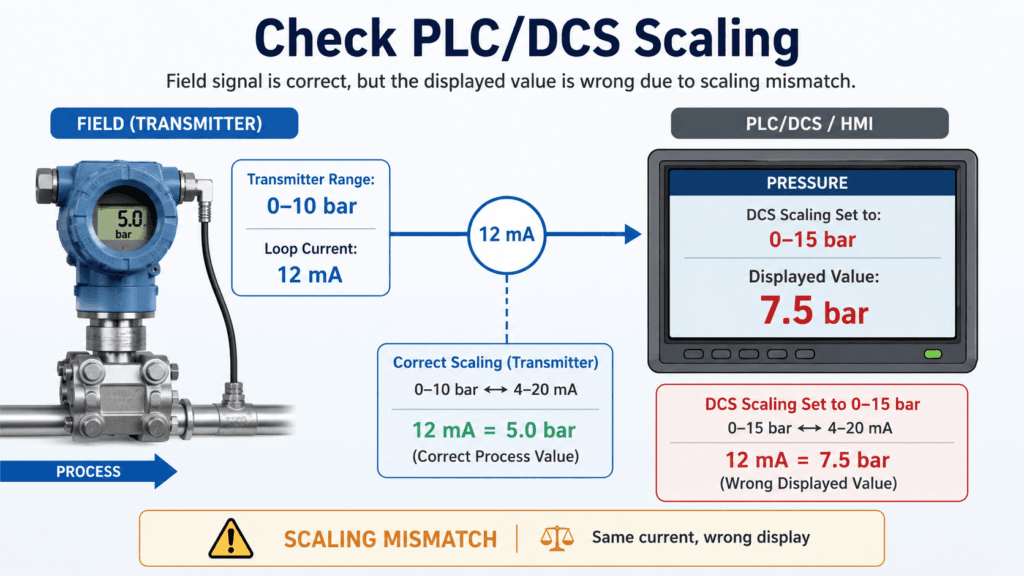
This is one of the most overlooked areas.
Sometimes the transmitter output is correct.
The loop current is correct.
The analog input card is receiving the signal.
But the value on the HMI is wrong.
In that case, the issue may be scaling.
For example, the transmitter may be configured for 0–10 bar, but the PLC/DCS scaling may be set for 0–16 bar. Or the transmitter range may have been changed during calibration, but the control system scaling was not updated.
The displayed value then becomes misleading.
This is not a transmitter fault.
It is an engineering data mismatch.
That is why range verification is important. The transmitter range, calibration sheet, PLC/DCS scaling, HMI display range, and alarm setpoints should all be consistent.
A small mismatch can create a big troubleshooting headache.
Ask What Changed Recently
When a signal suddenly becomes abnormal, I always like to ask:
What changed recently?
Recent maintenance can create clues.
Was the transmitter calibrated?
Was the impulse line cleaned?
Was the cable disconnected?
Was the junction box opened?
Was the PLC card replaced?
Was the DCS logic modified?
Was the range changed?
Was nearby equipment installed?
Was there welding or construction work nearby?
Many field problems are not random. They are connected to recent work.
This does not mean someone made a mistake intentionally. It only means the system changed, and the loop may have been affected.
In troubleshooting, recent history is often as important as the measurement value itself.
A Practical Field Sequence
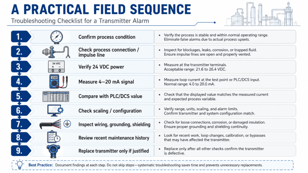
When I troubleshoot a transmitter alarm, I prefer a simple sequence.
First, confirm whether the process condition is real.
Second, check the process connection and sensing line.
Third, verify transmitter power supply.
Fourth, measure the 4–20 mA signal.
Fifth, compare field signal with PLC/DCS value.
Sixth, check scaling and configuration.
Seventh, inspect wiring, grounding, shielding, and junction boxes.
Eighth, review recent maintenance or modification history.
Finally, decide whether transmitter replacement is justified.
This sequence is not complicated.
But it prevents one dangerous habit:
Replacing parts before understanding the loop.
Replacing the Transmitter May Still Be Correct
The point is not to avoid transmitter replacement.
Sometimes replacement is the right answer.
A sensor diaphragm may be damaged.
Electronics may fail.
Moisture may enter the housing.
Terminals may be corroded.
The transmitter may no longer calibrate properly.
The output may be unstable even with a simulated input.
In those cases, replacement is reasonable.
But the decision should come after checking the loop, not before.
Good troubleshooting is not about moving slowly.
It is about moving in the right order.
Final Thought
A transmitter alarm is not a conclusion.
It is the beginning of an investigation.
Before replacing the transmitter, check the loop:
Process side.
Power supply.
Wiring.
Grounding.
Signal current.
PLC/DCS scaling.
Recent maintenance history.
Because in the field, the fastest answer is not always the safest answer.
And a good transmitter can still show a bad value if the loop around it is not healthy.