
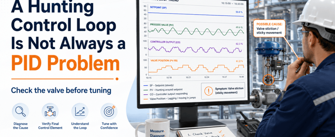
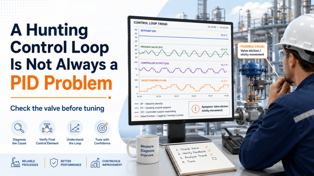
A control loop may be hunting because the valve is sticking, not because the PID is badly tuned.
When a process value repeatedly moves above and below the setpoint, the controller is often blamed first.
The proportional gain may look too aggressive.
The integral action may look too fast.
The operator may ask for the loop to be tuned again.
Changing the PID parameters may calm the trend temporarily.
But if the control valve is not following the controller output properly, tuning the PID does not remove the real problem.
It only teaches the controller to react differently to a valve that still does not move correctly.
Before changing the PID, I prefer to ask one simple question:
Is the valve actually following the controller output?
What a Hunting Loop Looks Like
A hunting loop does not settle smoothly around the setpoint.
Instead, the process value rises above the setpoint, falls below it, and continues repeating the same movement.
The controller output may also move continuously up and down.
At first glance, this can look like poor PID tuning.
And sometimes it is.
But the same pattern can also appear when the final control element responds inconsistently.
For example:
- The controller increases its output.
- The valve does not move because of friction.
- The process value remains unchanged.
- The controller increases its output further.
- The valve suddenly breaks free and moves too far.
- The process overshoots.
- The controller reverses its output.
- The same sequence happens in the opposite direction.
The controller appears aggressive.
But it may only be reacting to a valve that moves in steps instead of moving smoothly.
Controller Output Is Not Valve Position
This distinction is important.
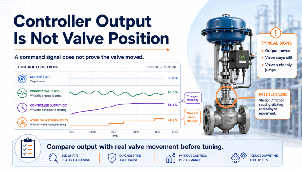
The controller output is a command.
It does not prove that the valve actually moved.
A DCS may show a controller output of 45 percent, but the valve may still be physically near 40 percent.
The output may then increase to 48 percent before the valve finally moves.
When it does, the valve may jump beyond the position needed by the process.
That lost motion can come from:
- Valve stiction
- Mechanical deadband
- Packing friction
- Loose feedback linkage
- Positioner calibration problems
- Actuator problems
- Unstable instrument air
- I/P converter problems
This is why I do not rely only on the controller output trend.
I want to compare at least three signals:
- Setpoint
- Process value
- Controller output
When available, I also add:
- Actual valve-position feedback
The relationship between these signals often tells more than the PID values themselves.
The Pattern of Valve Stiction
Valve stiction occurs when static friction prevents the valve stem from moving smoothly.
The controller output changes, but the valve remains in the same position.
Pressure continues building inside the actuator until the force becomes strong enough to overcome the friction.
The valve then jumps.
This creates a recognizable pattern:
- Controller output changes gradually
- Valve position remains almost fixed
- Valve position suddenly jumps
- Process value responds too strongly
- Controller output reverses
- The cycle repeats
If I see that pattern, I become cautious about changing the PID.
Reducing the controller gain may make the oscillation smaller.
Increasing the integral time may make the loop slower.
But the valve still sticks.
The trend may look calmer while the mechanical problem remains.
That is not a complete solution.
Deadband Can Create a Similar Problem
Deadband means the controller output must change by a certain amount before the final control element responds.
This is especially noticeable when the controller reverses direction.
For example, the output may decrease from 50 to 47 percent, but the valve position may not change.
The output decreases further to 44 percent, and only then does the valve begin moving.
This gap can come from mechanical play, worn linkage, positioner problems, or actuator characteristics.
A small amount of deadband may not cause a serious problem in a slow process.
But in a sensitive pressure or flow loop, it can create continuous cycling around the setpoint.
Again, changing the PID may change the symptom without correcting the lost motion.
Check the Instrument Air
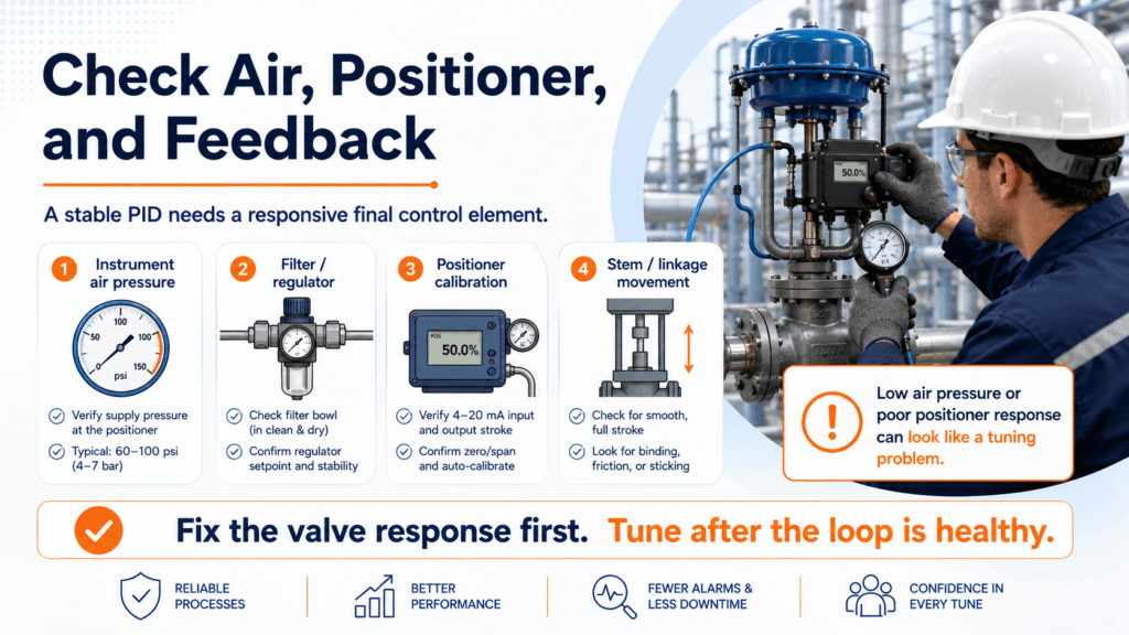
A pneumatic control valve depends on healthy instrument air.
Low pressure, moisture, contamination, or a blocked filter regulator can make valve response slow or inconsistent.
The valve may move normally during a workshop test but behave differently during actual plant operation.
The problem may appear only when:
- Several air-operated devices move at the same time
- Header pressure drops
- The filter becomes partially blocked
- Moisture accumulates
- Ambient temperature changes
- A small air leak becomes significant
Before blaming the PID or positioner, check the air supply under actual operating conditions.
Verify:
- Supply pressure
- Pressure stability
- Filter-regulator condition
- Air leakage
- Tubing condition
- Moisture or contamination
- Actuator pressure during movement
A stable controller cannot compensate for an unstable energy source driving the valve.
Check the Positioner and Feedback
A positioner receives the control command and tries to move the valve to the requested position.
If its calibration is incorrect, the valve may not match the controller output.
The feedback linkage may also be loose, bent, or incorrectly adjusted.
In that case, the positioner may report movement that does not accurately represent the valve stem.
Useful checks include:
- Command signal versus indicated position
- Actual stem movement
- Zero and span calibration
- Feedback linkage condition
- Positioner air output
- Travel calibration
- Positioner alarms or diagnostics
I prefer to watch the valve move through a controlled range when it is safe to do so.
A trend can show that something is wrong.
Actual movement can show how it is wrong.
Do Not Ignore the Mechanical Side
Instrumentation engineers often begin with signals because signals are visible from the control system.
But a control valve is also a mechanical device.
The stem can bind.
Packing can be overtightened.
The actuator can be damaged.
The valve trim can be worn.
The process fluid can cause buildup or deposits.
The valve may be exposed to forces that were not present when it was originally selected.
If the valve operates smoothly when disconnected from the process but struggles under actual differential pressure, the problem may be related to valve sizing, actuator force, or internal mechanical condition.
The PID controller cannot see these details.
It sees only that the process did not respond as expected.
A Practical Field Check
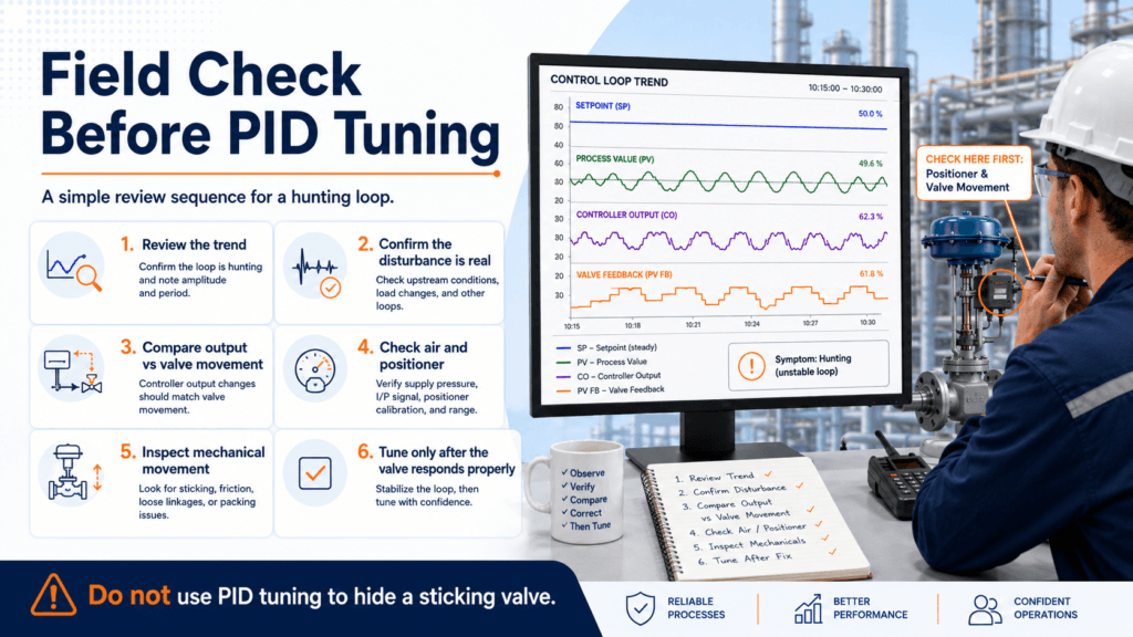
When a loop is hunting, I use a short review sequence before changing the tuning.
1. Review the Trend
Trend the setpoint, process value, controller output, and valve-position feedback together.
Look at the sequence of movement.
Does the output change before the valve moves?
Does the valve jump after remaining still?
2. Check Whether the Disturbance Is Real
Confirm that the oscillation is not being caused by another process condition.
Check upstream pressure, flow demand, pump operation, and related control loops.
3. Compare Output with Actual Valve Movement
Do not assume the command signal equals physical movement.
Verify the stem position or reliable feedback.
4. Check Instrument Air and the Positioner
Look for unstable supply pressure, leakage, calibration problems, or slow response.
5. Inspect Mechanical Movement
Check for friction, linkage problems, packing condition, and binding.
6. Tune Only After the Valve Responds Properly
Once the valve follows the controller output smoothly and predictably, PID tuning becomes meaningful.
When PID Tuning May Be the Right Next Step
PID tuning may still be necessary.
The original tuning may be poor.
The process operating range may have changed.
The valve or actuator may have been replaced.
The process dynamics may be different after a plant modification.
But I would rather tune a healthy loop than use tuning to hide an unhealthy valve.
A controlled test performed after the mechanical and instrumentation checks provides much better information than changing parameters during unstable operation.
The order matters.
First, confirm that the final control element can respond.
Then evaluate how the controller should command it.
Final Thought
A hunting control loop does not automatically mean the PID is wrong.
The controller may be sending the right command.
The valve may simply not be following it.
Before changing the gain or integral time, compare the controller output with the actual valve movement.
Check the air supply.
Check the positioner.
Check the linkage and mechanical condition.
Because good PID tuning cannot make a sticking valve move smoothly.
Sometimes the controller is not causing the oscillation.
It is revealing it.