
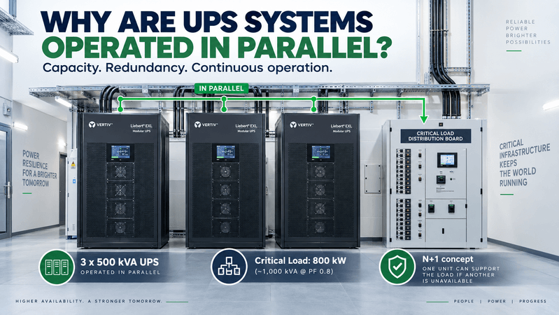
When I first looked at a large UPS system, one question seemed obvious.
Why use several UPS modules in parallel instead of one large UPS?
The first reason is simple.
Capacity.
If one UPS module cannot support the required critical load, several UPS modules can operate together and share the load.
But in critical power systems, capacity is only half of the story.
Parallel UPS systems can also provide something much more important:
Redundancy.
The ability to keep supplying the critical load even when one UPS module becomes unavailable.
One UPS Can Be Enough — Until It Isn’t
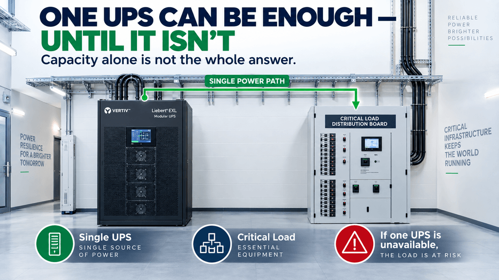
Suppose a facility has a critical load that could be supplied by one large UPS.
From a capacity point of view, that may be perfectly acceptable.
But then another question appears.
What happens if that UPS:
- Trips
- Develops an internal fault
- Needs maintenance
- Has to be isolated
- Needs replacement
If there is only one UPS in the power path, taking that UPS out of service may also put the critical load at risk.
So critical power design asks more than:
“Do I have enough UPS capacity?”
It also asks:
“Can I still support the load if one UPS becomes unavailable?”
That is where parallel UPS architecture becomes interesting.
Parallel UPS Modules Share the Load
Consider a simplified example.
The critical load is:
800 kW
Assume the load power factor is:
0.8
The apparent power requirement is therefore approximately:
1,000 kVA
Now suppose each UPS module is rated:
500 kVA
With two UPS modules operating in parallel:
500 kVA + 500 kVA = 1,000 kVA
The two modules together can provide the required 1,000 kVA system capacity.
In this example, two UPS modules are the minimum number required to support the critical load.
This required capacity is called:
N
So:
2 × 500 kVA = 1,000 kVA = N
There is enough capacity to support the load.
But there is no redundant UPS module.
Now Add One More UPS
Suppose another identical 500 kVA UPS module is installed.
Now we have:
3 × 500 kVA = 1,500 kVA installed capacity
But the load still requires only:
1,000 kVA
Only two UPS modules are actually required to support the load.
The third module provides additional capacity beyond N.
So the configuration becomes:
N + 1
In this example:
N = 2 × 500 kVA
+1 = 1 × 500 kVA
Installed = 3 × 500 kVA
The important point is not simply that we now have 1,500 kVA installed.
The important point is that the full critical load can still be supported even if one 500 kVA UPS module becomes unavailable.
What Happens If One UPS Module Trips?
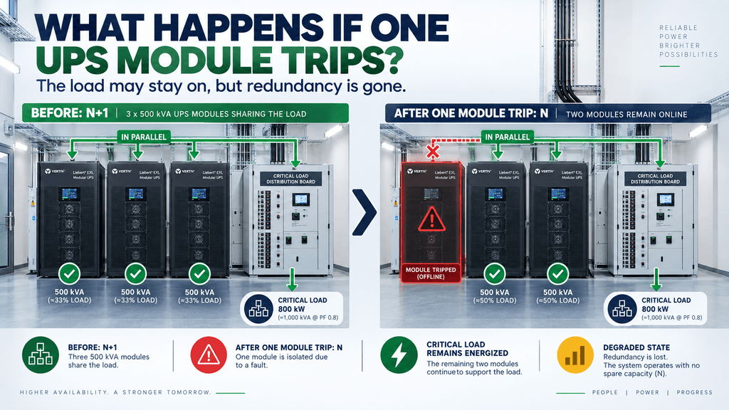
During normal operation, the three parallel UPS modules share the load.
The exact load sharing depends on the UPS control system, but conceptually the total load is distributed among the operating modules.
Then one module trips.
The system changes from:
3 × 500 kVA available
to:
2 × 500 kVA available
The remaining UPS capacity is:
1,000 kVA
That is still enough to support the required critical load in our example.
So the load remains energized.
No shutdown.
No interruption caused simply by the loss of that one UPS module.
This is the practical value of N+1 redundancy.
But something important has changed.
Before the trip:
N+1 available
After the trip:
Only N remains
The critical load is still running.
But the redundancy is gone.
The system is now operating in a degraded condition.
That leads to an important idea in critical power systems:
No outage does not mean no problem.
Capacity and Redundancy Are Different Questions
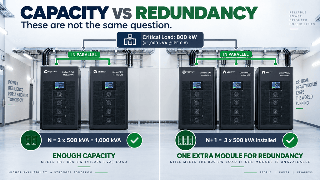
This is probably the easiest way to understand parallel UPS architecture.
There are two different questions.
Question 1: Capacity
Can the UPS system support the required load?
In our example:
Required UPS capacity = 1,000 kVA
Two 500 kVA UPS modules can provide:
1,000 kVA
Capacity requirement?
Yes.
Question 2: Redundancy
Can the system still support the required load after one UPS becomes unavailable?
With only two 500 kVA UPS modules:
One module fails.
Remaining capacity:
500 kVA
That is not enough.
So:
Capacity = Yes
Redundancy = No
Now install three 500 kVA UPS modules.
One module fails.
Remaining capacity:
1,000 kVA
The load can still be supported.
Now:
Capacity = Yes
Redundancy = Yes
That is the basic idea behind N+1.
Redundancy Is About Surviving Equipment Unavailability
The extra UPS module is useful not only when something fails.
Equipment can become unavailable for many reasons.
A UPS may be:
- Faulted
- Isolated
- Under inspection
- Under maintenance
- Being repaired
- Temporarily removed from service
If the remaining UPS modules still have enough capacity to carry the critical load, operation can continue.
This is one of the fundamental ideas behind resilient power systems:
A single equipment failure should not automatically become a system shutdown.
Parallel UPS Can Also Help With Maintenance
UPS equipment eventually requires maintenance.
Fans.
Capacitors.
Power modules.
Control boards.
Filters.
Internal connections.
And other components.
If sufficient redundancy is available, one UPS module may be removed from service while the remaining modules continue supporting the load.
For example:
Normal condition:
3 × 500 kVA → N+1
One UPS isolated for maintenance:
2 × 500 kVA → N
The load can continue operating.
However, there is an important distinction.
Having N+1 UPS modules does not automatically mean the entire system can always be maintained without interruption.
That depends on the complete architecture.
The engineer still needs to consider:
- Bypass arrangement
- Isolation devices
- Input and output distribution
- Common switchboards
- Remaining UPS capacity
- Operating procedures
UPS module redundancy is only one part of the system.
More UPS Modules Do Not Automatically Mean a Redundant System
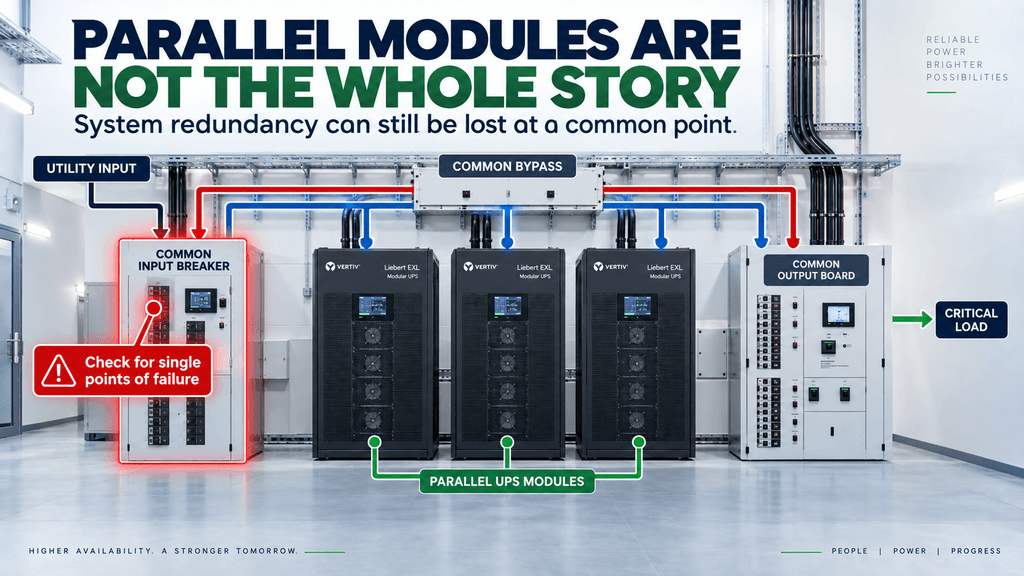
This is where things become more interesting.
Imagine three UPS modules configured as N+1.
It looks redundant.
But suppose all three UPS modules depend on one common component.
For example:
One common input breaker
or
One common bypass source
or
One common output switchboard
If that common component fails, all three UPS modules may still lose the ability to supply the critical load.
So simply counting UPS modules is not enough.
Three UPS modules do not automatically mean:
“This power system is fully redundant.”
Redundancy needs to be considered at the system level.
A better question is:
“What happens to the critical load if this component fails?”
That question starts to reveal potential single points of failure.
Parallel Operation Requires Load Sharing
There is another important part of parallel UPS operation.
The modules must share the load correctly.
You cannot simply connect several independent UPS outputs together and expect them to operate properly.
Parallel-capable UPS systems use coordinated controls so the modules operate together.
During normal operation:
UPS 1 + UPS 2 + UPS 3
↓
Share the critical load
If UPS 3 trips:
UPS 1 + UPS 2
↓
Automatically accept the additional load
↓
Critical load remains energized
The transition needs to occur without disrupting the load.
So parallel UPS operation involves both:
Power capacity
and
Control coordination
One Important Sizing Note
The example above uses kVA to explain UPS system capacity.
However, actual UPS selection should not look at kVA alone.
A UPS normally has both:
kVA rating
and
kW rating
The connected load also has a real power requirement and a power factor.
For example, an 800 kW load at a power factor of 0.8 corresponds to approximately 1,000 kVA.
But actual systems may operate at a higher power factor, and many modern UPS systems have kW ratings much closer to their kVA ratings.
So during actual design review, both should be checked:
Required kVA ≤ Available UPS kVA
and
Required kW ≤ Available UPS kW
The example here is simply intended to explain the concept of parallel capacity and redundancy.
The Bigger Lesson
Parallel UPS systems are not just about increasing capacity.
They allow critical loads to continue operating when one UPS module becomes unavailable.
That is the more important idea.
And the same thinking appears throughout critical power systems.
UPS modules.
Generators.
Transformers.
Distribution paths.
Cooling systems.
Control systems.
The question is always similar:
What happens if one component becomes unavailable?
Critical power engineering is not only about having enough capacity during normal operation.
It is about understanding how the system behaves after something goes wrong.
That is why several UPS modules operating in parallel can offer something that one large UPS cannot easily provide.
Not just more capacity.
But:
Continuity through redundancy.
Field Checklist
When reviewing a parallel UPS system:
□ Identify the critical load in both kW and kVA
□ Confirm the UPS module kVA and kW ratings
□ Determine how many UPS modules are required for N capacity
□ Identify the number of additional redundant modules
□ Confirm remaining capacity after one UPS module is unavailable
□ Check how the remaining modules accept and share the load
□ Identify common components that may still create a single point of failure
□ Review bypass and isolation arrangements
□ Confirm alarms for UPS module failure and loss of redundancy
Safety Note:
Parallel UPS systems may contain multiple energized sources and can remain energized through normal, bypass, battery, or parallel paths even when one module is isolated. Switching, bypass operation, testing, and maintenance should only be performed by authorized personnel according to approved procedures, manufacturer instructions, site electrical safety requirements, and applicable standards.