
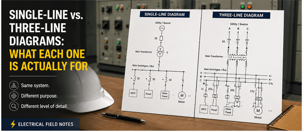
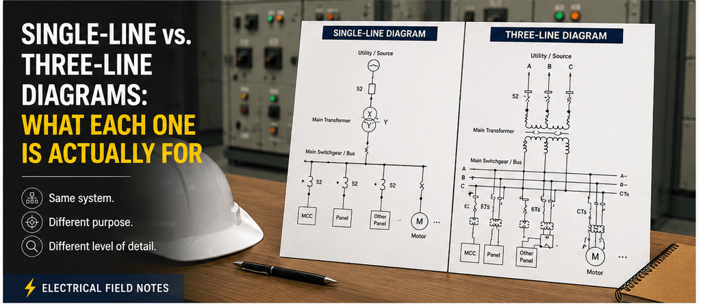
I was looking at an electrical drawing and realized something simple.
A single-line diagram and a three-line diagram may describe the same electrical system.
But they are not trying to answer the same question.
If I want to understand:
“Where does the power come from, and where does it go?”
I open the single-line diagram.
If I need to understand:
“How is each phase actually connected through CTs, PTs, meters, and protection?”
I need more detail.
That is where the three-line diagram becomes useful.
The difference is not simply:
Simple drawing vs. detailed drawing.
The real difference is:
System view vs. phase-by-phase view.
What a Single-Line Diagram Is Trying to Show
A three-phase power system physically has multiple conductors.
But drawing every phase throughout an entire plant would make the drawing unnecessarily complicated.
So the single-line diagram simplifies the system.
One line represents the three-phase power path.
That makes it much easier to see:
- Utility or generator sources
- Transformers
- Main switchgear
- Busbars
- Circuit breakers
- MCCs
- Major loads
- Bus ties
- Voltage levels
- Equipment ratings
- Protection devices
The main purpose is to understand the architecture of the power system.
When I open an SLD, I am usually asking questions like:
- What feeds this MCC?
- Which transformer supplies this bus?
- What happens if this breaker opens?
- Where is the bus tie?
- What loads will be lost during a shutdown?
- Which breaker is upstream?
- Where should the fault current flow?
That is exactly why the single-line diagram is so useful.
It removes unnecessary detail so the system structure becomes visible.
But That Simplification Has a Cost
The strength of an SLD is also its limitation.
Three phases are compressed into one line.
That means many phase-specific details disappear.
Suppose a CT is shown on the single-line diagram.
I may understand that a feeder has CTs for protection or metering.
But several questions may still remain:
- Which CT is connected to each phase?
- What is the CT polarity?
- How are the CT secondary circuits connected?
- Where is the CT secondary grounded?
- Are separate cores used for protection and metering?
- How are the PT or VT phases connected?
The SLD was never intended to answer every one of those questions.
For that, we need another level of detail.
What a Three-Line Diagram Adds
A three-line diagram expands the three-phase system.
Instead of representing the system as one equivalent line, it shows the phases individually:
Phase A
Phase B
Phase C
Depending on the system, neutral and grounding connections may also be shown.
This allows the drawing to show more detailed phase relationships for equipment such as:
- CTs
- PTs / VTs
- Protection relays
- Meters
- Breakers
- Fuses
- Grounding connections
- Transformer windings
This becomes particularly useful around switchgear, metering, and protection systems.
A Simple Example: Current Transformers
Imagine a feeder protected by an overcurrent relay.
The SLD might show the CTs and relay as part of the feeder protection.
That is enough to understand the protection concept.
But during commissioning or troubleshooting, I may need to know much more.
A three-line diagram can show:
Phase A CT → Phase A current circuit
Phase B CT → Phase B current circuit
Phase C CT → Phase C current circuit
It may also show CT polarity and secondary connections.
Now I can begin checking questions such as:
- Is each phase connected correctly?
- Is one CT polarity reversed?
- Is the secondary common connection correct?
- Is the grounding point where it should be?
- Are the CT circuits arranged as intended?
Those are questions that a single-line diagram may simply not answer.
The Same Equipment Can Look Very Different
Take a three-phase circuit breaker.
On the SLD, it may appear as one breaker symbol.
Simple.
Clean.
Easy to understand.
But physically, the breaker switches three phases.
A three-line diagram can show each phase separately and how it relates to the surrounding circuit.
Neither drawing is wrong.
They are simply showing the same system at different levels of abstraction.
That distinction matters.
Single-Line Diagram = System Thinking
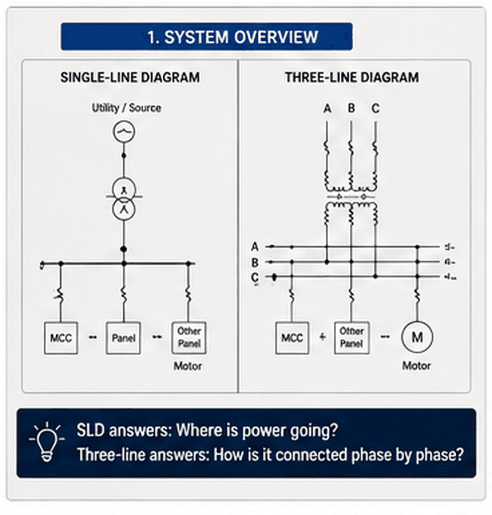
I think of the single-line diagram as the map of the electrical system.
It helps me understand hierarchy.
For example:
Utility
↓
Transformer
↓
Main Switchgear
↓
MCC
↓
Motor Feeder
↓
Motor
From this drawing, I can think about:
- Power flow
- Fault-current paths
- Protection hierarchy
- Load distribution
- System redundancy
- Shutdown impact
- Switching sequence
For troubleshooting large electrical events, this is usually where I start.
Three-Line Diagram = Phase-by-Phase Thinking
The three-line diagram takes me one level deeper.
Now I am thinking about:
- Individual phases
- CT polarity
- PT connections
- Phase relationships
- Protection current circuits
- Metering circuits
- Neutral and grounding connections
So if the SLD answers:
“How is the system arranged?”
the three-line diagram answers something closer to:
“How is this three-phase circuit actually connected?”
Which Drawing Should I Open?
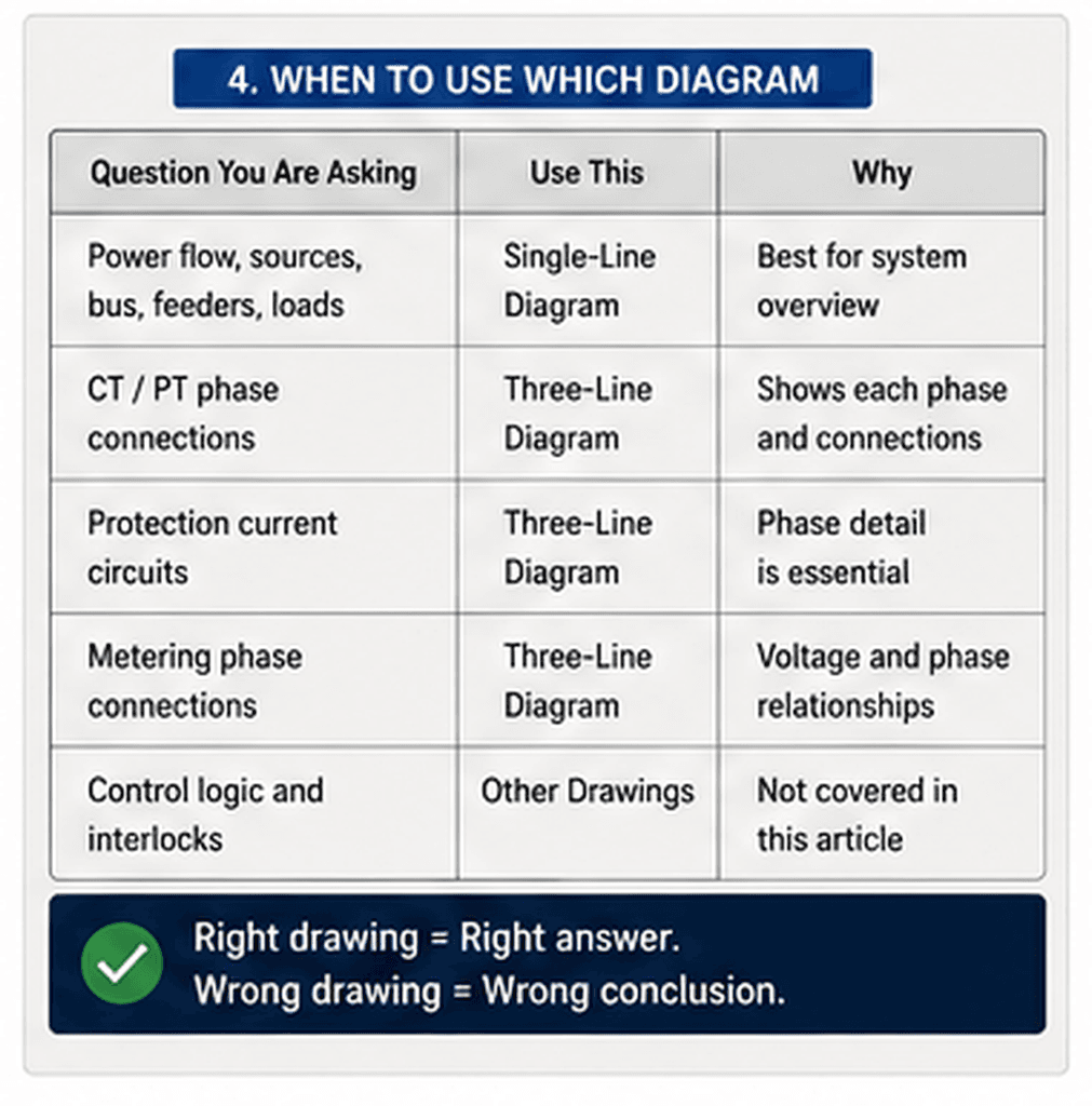
It depends on the question.
If I want to know:
What supplies this MCC?
→ Single-line diagram.
If I want to know:
Which transformer supplies this bus?
→ Single-line diagram.
If I want to know:
Where is the upstream protective device?
→ Single-line diagram.
If I want to know:
How are the three CT phases connected?
→ Three-line diagram.
If I want to know:
How are PT or VT phases arranged?
→ Three-line diagram.
If I want to check:
Phase-specific protection or metering connections
→ Three-line diagram.
This is a useful habit in troubleshooting.
Before studying a drawing for twenty minutes, ask:
“Is this drawing actually designed to answer my question?”
More Detail Is Not Always Better
It is tempting to think that the more detailed drawing must be the better drawing.
Not necessarily.
Imagine trying to understand an entire plant distribution system with every phase and every connection drawn individually.
You would quickly lose the system architecture.
That is why simplification matters.
The SLD deliberately hides detail.
The three-line diagram deliberately restores some of it.
The important question is not:
“Which drawing has more information?”
It is:
“Which level of information do I need right now?”
My Practical Rule
When I first need to understand an unfamiliar electrical system, I usually start with the single-line diagram.
It gives me the big picture.
Then, when the problem becomes phase-specific or protection-specific, I move to the three-line diagram.
I think of the transition like this:
System → Phase
The SLD gives me the system.
The three-line diagram lets me zoom into the individual phases.
They are not competing drawings.
They complement each other.
Final Thought
The single-line diagram is not an incomplete three-line diagram.
And the three-line diagram is not simply a better single-line diagram.
They serve different purposes.
The SLD removes phase detail so we can understand the system.
The three-line diagram restores phase detail so we can understand the three-phase connections.
That is the important distinction.
When troubleshooting, the best drawing is not the drawing with the most information.
It is the drawing that answers the question you are trying to solve.
Safety Notice
Electrical drawings are important engineering references, but they should not be treated as proof that field conditions are identical to the drawing.
Before electrical inspection, testing, isolation, or maintenance:
- Confirm the latest approved drawing revision
- Verify equipment identification in the field
- Follow approved electrical safety and LOTO procedures
- Consider alternate, control, UPS, and backfeed sources
- Verify the actual electrical condition using approved procedures where required
Electrical work should only be performed by qualified personnel.