
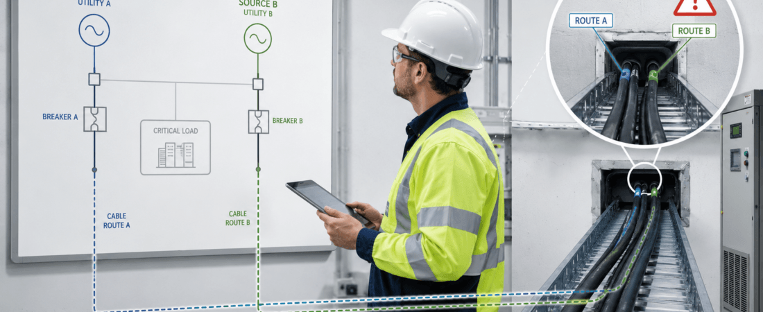
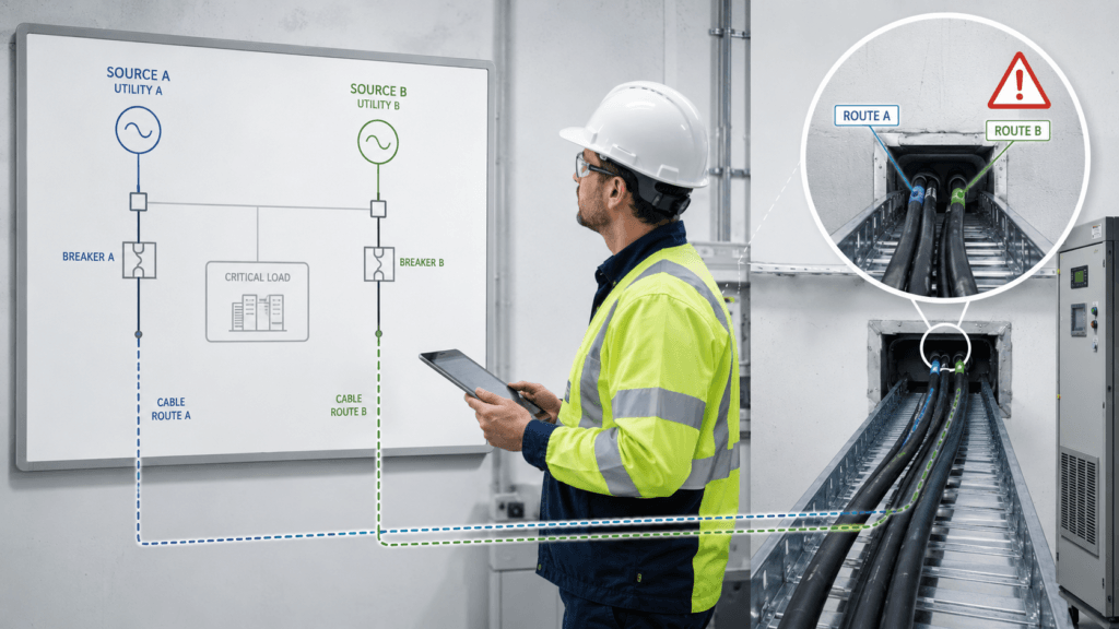
Two sources.
Two breakers.
Two cables.
On the drawing, the system looked reassuring.
It had the kind of words engineers and managers like to hear: redundant, dual-fed, backup available, improved reliability.
But during one walkdown, I noticed something that changed how I looked at the whole arrangement.
Both cable routes entered the building through the same opening.
From a distance, the system looked duplicated.
From a failure point of view, it was not as independent as it first appeared.
That is one of the uncomfortable truths about redundancy in electrical systems.
Sometimes we count components and feel safe.
But reliability does not come from the number of components alone.
It comes from how independent their failure paths really are.
Redundancy Looks Good on a Single-Line Diagram
A single-line diagram is a useful tool.
It helps us understand sources, feeders, switchboards, transfers, and normal operating philosophy.
But a single-line diagram can also make a system look more independent than it really is.
You may see:
- Source A
- Source B
- Two incomers
- Two cables
- Two breakers
- A tie arrangement
- Separate labels
And technically, all of that may be true.
Still, the important question is not just:
Do I have two sources?
It is also:
Can one real-world event disable both paths at the same time?
That question usually becomes clearer during a field walkdown than during a drawing review.
Because the field shows what the drawing compresses.
Cable routing.
Room arrangement.
Penetrations.
Common supports.
Drainage.
Ventilation.
Fire separation.
Maintenance access.
All the messy physical details that determine whether the two paths are truly separate—or only appear separate.
Two Cables in the Same Route Are Not Two Independent Paths
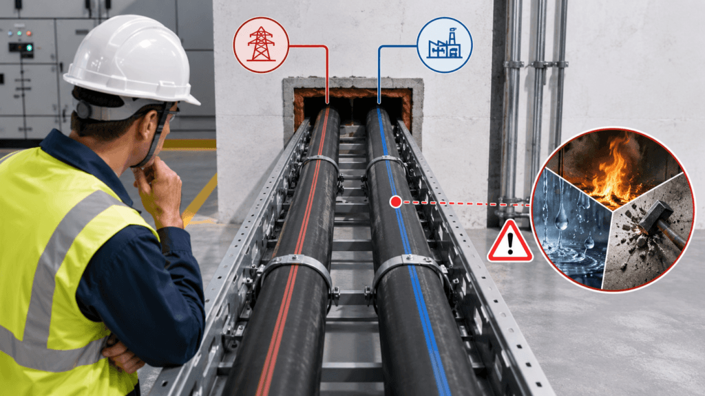
This is the first thing I check.
If both “independent” power cables run through the same trench, tray, tunnel, duct bank, or wall penetration, I immediately become more cautious about calling the design redundant.
Because one event may affect both cables:
- Fire in one tray
- Water ingress in one trench
- Mechanical damage during nearby work
- Heat exposure
- Chemical exposure
- Cable support failure
- Poor sealing at one penetration
- A contractor cutting the wrong route
None of these failures care that the cables belong to two different sources.
If they share the same physical path, they share the same exposure.
That does not mean the design has no value.
It does mean the actual redundancy is weaker than the drawing suggests.
I have become careful with this distinction:
Duplicate equipment is not always independent equipment.
Common Rooms Can Become Common Failure Zones
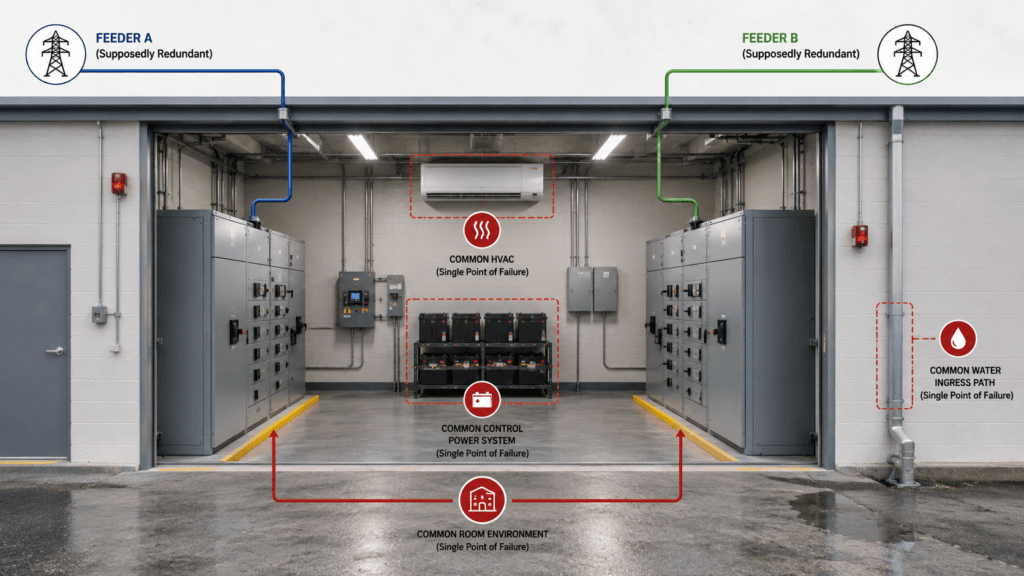
Sometimes the cables are separated for most of the run, but both terminate in the same electrical room, rack room, or switchboard area.
Again, the system may still be better than a single-source design.
But I want to understand what failures are still common to both paths.
For example:
- One room fire
- One room flooding event
- One HVAC failure causing temperature rise
- One condensation problem
- One maintenance error
- One internal arc event
- One construction activity
- One door left open to a harsh environment
When two redundant paths depend on the same room environment, the room itself becomes a shared risk.
This matters more than people sometimes expect.
A well-designed power path can still be compromised by something as ordinary as poor drainage, humid air ingress, roof leakage, or inadequate cooling.
The electrical path and the environmental path are often more connected than the drawing shows.
Shared Support Systems Quietly Reduce Redundancy
I have also learned to look beyond the power path itself.
Sometimes two power sources are electrically separate, but they still depend on the same support system.
That support system can quietly become the real single point of failure.
Examples include:
- Common control power supply
- Common battery system
- Common DC charger
- Common protection relay power
- Common PLC or automation interface
- Common cooling or ventilation system
- Common communication network
- Common fuel system for backup generation
- Common transfer logic
- Common trip circuit
On paper, the feeders may look independent.
Operationally, they may still fail together because one shared support system disappears.
This is why I no longer look at redundancy as a pure cable-and-breaker question.
I try to ask:
What invisible dependency would make both paths unavailable at the same time?
That question usually leads to better conversations.
Maintenance Reality Matters Too
There is another practical side to redundancy that drawings do not show well.
Can the two paths be maintained independently?
Or does maintenance on one path expose the other?
I have seen situations where a system looked redundant during normal operation, but during inspection, testing, isolation, or switching, the real independence became much weaker.
Questions I like to ask are:
- Can one path be safely isolated while the other remains fully available?
- Does maintenance require both sections to be opened in the same room?
- Are both paths exposed when one contractor opens the same trench or penetration area?
- Does testing one source disturb a common panel or common control circuit?
- Are the labels, procedures, and access arrangements clear enough to prevent cross-impact?
True redundancy should not exist only during a presentation slide or under ideal operating mode.
It should survive maintenance, testing, inspection, and human error as much as reasonably possible.
Drawings Can Say “Separate” While the Field Says “Shared”
This is one of the reasons I still like field walkdowns.
Not because drawings are unimportant.
Because drawings and reality drift apart over time.
A cable may have been rerouted.
A temporary tray may have become permanent.
A fire barrier may have been removed and never restored.
A spare feeder may now share a tray with a normal feeder.
A new penetration may have been added during a shutdown.
A room may now contain equipment that was never part of the original design.
If you only review the latest PDF, you may conclude that the system is still robust.
If you walk the route, you may notice that the two “independent” paths now touch each other far more than intended.
That does not always mean somebody made a major mistake.
Sometimes the system evolved gradually, one practical decision at a time.
But reliability often gets weakened gradually too.
That is why I do not like using the word redundancy casually.
I want to see it.
What I Look for During a Redundancy Walkdown
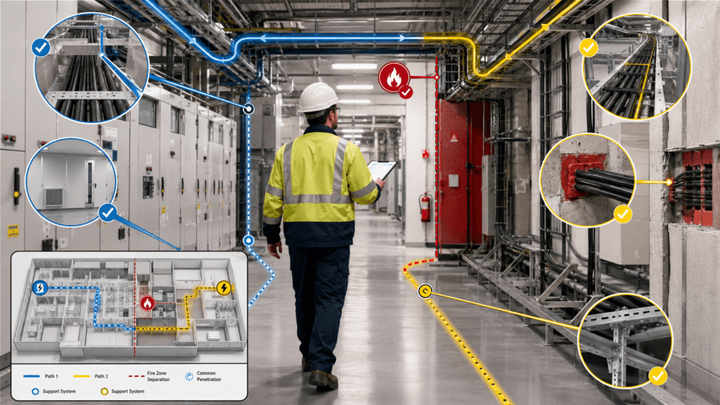
When I review a supposedly redundant power arrangement, I try to trace both paths as completely as possible.
Not just electrically.
Physically and operationally too.
I usually look at the following.
Upstream Separation
- Do the two paths really come from different upstream sources?
- Or do they split only at a lower level while still relying on the same transformer, same board, or same upstream switchgear section?
Cable Routing
- Do the cables follow different trays, trenches, shafts, or penetrations?
- Do they run close together for long distances?
- Is there a shared choke point?
Room and Fire Zone Separation
- Do both paths pass through the same room?
- The same fire zone?
- The same flood-prone or condensation-prone area?
Common Environmental Exposure
- Are both paths vulnerable to the same water ingress point?
- The same roof leak?
- The same HVAC failure?
- The same hot zone?
Common Support Systems
- Do both depend on one control power source?
- One battery?
- One protection circuit?
- One communication link?
- One cooling system?
Operational Independence
- Can one path stay live and protected while the other is maintained?
- Are switching and isolation procedures clear?
As-Built Reality
- Does the field installation still match the design intent?
- What changed after commissioning?
The point of this review is not to criticize the design for not being perfect.
The point is to understand what kind of failure the system can actually tolerate.
That is a much more useful question than whether the drawing carries the word “redundant.”
A Small Change Can Remove a Big Assumption
What makes these systems tricky is that the weakness is not always dramatic.
Sometimes one wall penetration.
One shared tray section.
One common UPS.
One common room.
One unrepaired firestop.
One cooling dependency.
That is enough to change the real reliability picture.
People tend to think of redundancy as something major and visible.
But losing redundancy is often quiet.
It happens in small decisions:
- “Let’s route this cable here for convenience.”
- “This temporary support will do for now.”
- “We’ll reseal that opening later.”
- “Both panels can use the same small UPS.”
- “It’s easier to install both paths in the same tray section.”
Each decision may sound reasonable at the time.
Taken together, they can defeat the original design intent.
What This Means in Practice
I do not think the lesson is that redundancy is useless unless it is perfect.
That would be unrealistic.
The lesson is that redundancy should be described honestly.
If two sources share one cable route, say so.
If two feeders rely on one room environment, acknowledge it.
If the system is robust against one kind of failure but still exposed to another, make that visible.
Engineers do not need a perfect system to make good decisions.
They need a clear understanding of what the system can and cannot tolerate.
That is where practical reliability starts.
My Field Reminder
When I see a design labeled redundant, I try not to stop at the labels.
I ask a few uncomfortable questions.
What do these two paths share?
Where do they come close?
What single event could still disable both?
What would maintenance do to this arrangement?
And does the field installation still reflect the original idea?
Those questions have saved me from feeling too comfortable too early.
Final Thought
Two sources do not guarantee two independent paths.
Two cables do not guarantee two separate failures.
And a redundant label does not guarantee resilient operation.
In the field, redundancy is tested by fire, water, heat, maintenance, mistakes, and time.
That is why I have come to trust walkdowns as much as drawings.
Because sometimes the most important reliability risk is not hidden inside a breaker or relay.
It is quietly sitting in one shared cable route that nobody questioned closely enough.
And one shared route can defeat an entire redundancy design.