
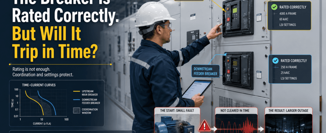
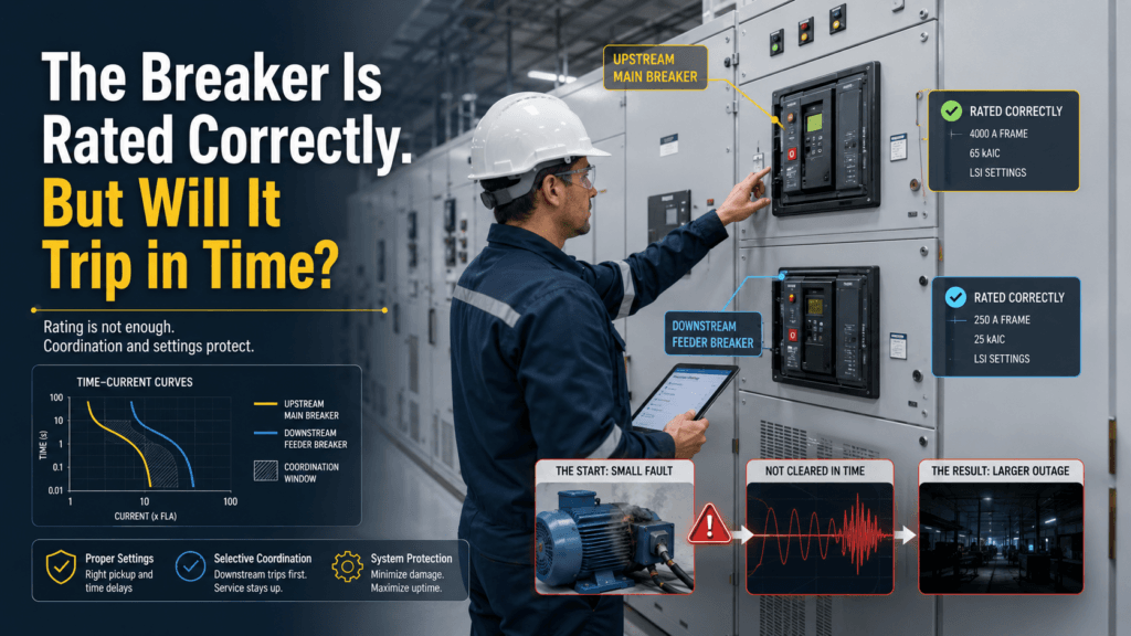
A small motor failed.
The motor feeder should have isolated the fault.
Instead, the main breaker opened.
A much larger section of the plant lost power because of a fault that began at one relatively small piece of equipment.
When we reviewed the system afterward, the breaker ratings did not immediately look wrong.
The feeder breaker was large enough for the motor load.
The main breaker had adequate current and interrupting ratings.
The cable size also looked acceptable.
On paper, the components appeared properly selected.
But protection is not only about whether each device has the correct rating.
The more important question is:
When a fault occurs, which device will trip—and how quickly?
That incident reminded me that a correctly rated breaker can still be part of a poorly protected system.
The Rating Plate Does Not Tell the Whole Story
When reviewing a breaker, it is easy to start with the numbers printed on the front.
Rated current.
Frame size.
Interrupting capacity.
Voltage rating.
Those numbers are important. But they do not fully describe how the breaker will behave during an actual fault.
Two breakers with suitable ratings can still operate in the wrong order.
A downstream breaker may respond too slowly.
An upstream breaker may have an instantaneous setting that overlaps the downstream protection.
A local motor protection relay may be installed but not configured correctly.
The circuit may therefore be electrically capable of carrying the load while still being poorly coordinated during abnormal conditions.
This is where I separate two different questions:
- Can the circuit carry the load safely?
- Can the protection isolate a fault before the damage spreads?
Passing the first test does not automatically mean it passes the second.
The Breaker That Should Trip First
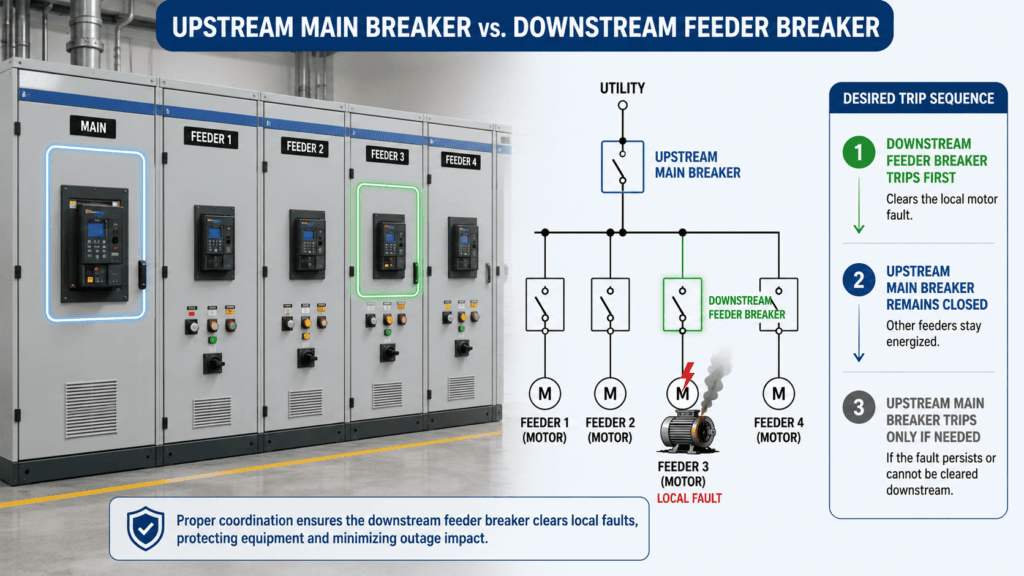
For most downstream equipment faults, I want the protection closest to the fault to operate first.
A motor fault should normally be cleared by the motor feeder protection.
A branch-circuit fault should normally be cleared by the branch breaker.
The upstream main breaker should remain closed unless the downstream device cannot clear the fault or the fault is located on the upstream section itself.
This is the basic idea of selectivity.
In the field, however, the system does not care what we intended.
It responds to the actual fault current, actual settings, actual time delays, and actual equipment condition.
If the downstream protection is disabled, incorrectly set, or slower than expected, the upstream device may clear the fault first.
The result is technically a successful fault interruption.
But operationally, it can be a poor outcome.
One small equipment failure becomes a larger production interruption.
A Setting Can Matter More Than the Breaker Size

After a breaker is selected, the settings determine how it behaves.
Depending on the device, those settings may include:
- Long-time pickup
- Long-time delay
- Short-time pickup
- Short-time delay
- Instantaneous pickup
- Ground-fault pickup and delay
- Motor overload current
- Motor starting allowance
- Stall or locked-rotor protection
- Phase-loss or current-imbalance protection
A breaker can have the correct frame size and still be badly set.
For example, a motor may require enough time to complete a normal start. If the protection is too sensitive, it may trip during healthy acceleration.
The natural response is often to raise the setting.
That may stop nuisance trips.
But if the setting is raised without reviewing the motor, cable, starting curve, and upstream protection, the local protection can become ineffective during a real fault.
This is where protection work becomes an engineering decision rather than a simple number adjustment.
The setting must tolerate normal operation without giving the fault unnecessary time to cause damage.
The Starting Current Complicates the Picture
Motors make coordination more interesting because normal starting current can be many times the running current.
The protection must distinguish between:
- A healthy motor starting
- A motor taking too long to accelerate
- A mechanically locked motor
- A phase-loss condition
- A short circuit
- A ground fault
If the trip curve crosses the normal starting region, nuisance trips are likely.
If it sits too far above the starting curve, the motor and cable may remain exposed longer than intended.
I do not like reviewing the protection setting without also checking the actual starting behavior.
Useful information includes:
- Measured running current
- Starting-current magnitude
- Starting duration
- Number of starts per hour
- Load acceleration characteristics
- Motor thermal limits
- Cable withstand
- Voltage drop during starting
A motor that starts in two seconds and a high-inertia load that needs fifteen seconds should not be treated as the same protection problem.
Is There Enough Fault Current to Operate the Protection?
This is another point that can be missed.
A breaker may have an instantaneous setting, but the available fault current at the far end of the circuit may not be high enough to enter that region.
Cable length and impedance reduce fault current.
A small fault near the load may therefore be cleared by the slower protection function rather than the instantaneous element.
That may be acceptable if the cable and equipment can withstand the clearing time.
But it needs to be checked.
I want to know:
- Available fault current at the bus
- Available fault current at the load end
- Cable size and length
- Transformer impedance
- System voltage
- Grounding arrangement
- Breaker or relay pickup values
- Expected clearing time
The breaker interrupting rating tells me whether it can safely interrupt a large fault.
It does not tell me whether a smaller downstream fault will make it trip quickly enough.
Those are different questions.
The Local Protection May Exist but Still Be Missing
One lesson from maintenance work is that “installed” does not always mean “active.”
A motor protection device may be physically present while:
- The current setting remains at its default
- The overload function is disabled
- The CT ratio is entered incorrectly
- The trip output is not wired
- The device is in alarm-only mode
- The bypass remains active after testing
- The setting was lost after replacement
- The new relay was never matched to the motor data
From the outside, the feeder looks protected.
The device powers up.
The display works.
No alarm is present.
But during a real fault, the system may behave very differently from the design intent.
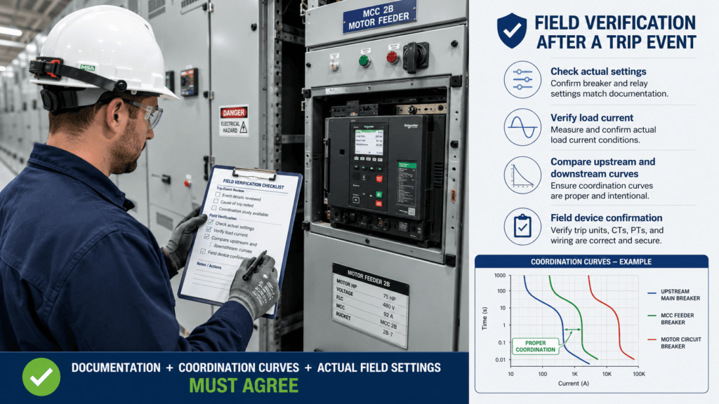
This is why I prefer to verify protection settings in the field rather than relying only on an old setting sheet.
The drawing tells me what should be installed.
The coordination study tells me what should be set.
The field device tells me what is actually protecting the equipment today.
All three need to agree.
Small Changes Can Break Coordination
Protection coordination is not something that can be completed once and forgotten forever.
The system changes.
A breaker is replaced with a different model.
A larger motor is installed.
A cable is extended.
A transformer is upgraded.
A relay firmware or setting group is changed.
A temporary feeder becomes permanent.
Someone raises a trip setting to stop repeated interruptions.
Each change may look reasonable by itself.
But it can alter the relationship between upstream and downstream protection.
I have learned to pay particular attention after:
- Breaker replacement
- Motor replacement
- Cable modification
- Transformer capacity increase
- MCC renovation
- Relay replacement
- Repeated nuisance-trip adjustments
- Temporary bypass work
- Plant expansion
A replacement breaker does not need to be defective to create a problem.
It only needs to behave differently from the device assumed in the original coordination study.
What I Review Before Approving a Setting
I am not trying to turn every maintenance decision into a large protection study.
But before approving or changing a setting, I want enough information to understand the consequence.
My review usually includes the following.
The Load
What is the real operating current?
Is the load continuous, cyclic, or intermittent?
Does the equipment experience high starting or inrush current?
The Cable
Can the cable carry the load?
Can it withstand the fault current until the protective device clears it?
The Equipment
What must be protected?
A cable, motor, transformer, heater, UPS, or busbar may have different thermal limits and operating characteristics.
The Available Fault Current
How much fault current is expected at the source and at the load end?
Will the intended protection function actually pick up?
The Upstream and Downstream Curves
Which device should operate first?
Is there enough separation between their trip curves?
Do the instantaneous regions overlap?
The Field Settings
Do the actual breaker and relay settings match the approved values?
Are the CT ratio, mode, and enabled functions correct?
Recent Changes
Has anything been replaced, bypassed, extended, or adjusted since the last review?
This does not eliminate every uncertainty.
But it prevents the breaker ampere rating from becoming the entire engineering decision.
What I Try Not to Do
Raise the Setting Just to Stop a Trip
A nuisance trip is a symptom.
Raising the pickup value may remove the symptom while also reducing protection.
Assume the Downstream Device Will Always Trip First
Coordination must be demonstrated through the curves, settings, and expected fault current.
Physical location alone does not decide the trip order.
Trust the Setting Sheet Without Checking the Device
Documents can be outdated.
Field devices can be replaced or reset.
Review Only the Maximum Short-Circuit Current
Maximum fault current is important for interrupting capacity.
Minimum fault current can be important for confirming that the protection will operate quickly enough.
Close the Investigation After a Successful Reset
A breaker that resets successfully has only confirmed that it can be closed again.
It has not explained why it opened or whether the protection sequence was correct.
Field Checklist: Before Approving a Breaker Setting
- Confirm the actual operating current
- Review starting or inrush current and duration
- Verify cable ampacity and thermal withstand
- Check available fault current at the bus and load end
- Confirm breaker interrupting capacity
- Compare upstream and downstream trip curves
- Review long-time, short-time, instantaneous, and ground-fault settings
- Check motor overload or local protection settings
- Confirm CT ratio and enabled protection functions
- Verify settings directly at the field device
- Review recent replacements and modifications
- Confirm which device is intended to trip first
- Record the approved values and revision date
- Recheck coordination after significant system changes
Final Thought
The breaker rating may be correct.
The cable may be correctly sized.
The equipment may operate normally for years.
But protection is tested during the few seconds when something goes wrong.
That is when the system reveals whether the intended device trips first, whether it trips quickly enough, and whether the fault remains local.
A good protection system does more than interrupt current.
It limits damage.
It preserves healthy parts of the plant.
And it prevents one small failure from becoming a much larger outage.
So when I review a breaker, I no longer stop at:
“Is the rating correct?”
I also ask:
When the fault comes, will the right device trip in time?