
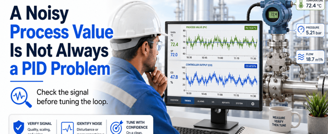

A controller cannot stabilize a measurement that is not trustworthy.
When a process value keeps fluctuating, the first reaction is often predictable.
“The PID is too aggressive.”
“Slow the loop down.”
“Add more filtering.”
“Reduce the proportional gain.”
Sometimes that is the correct direction.
But I have learned not to touch the tuning until I can answer one basic question:
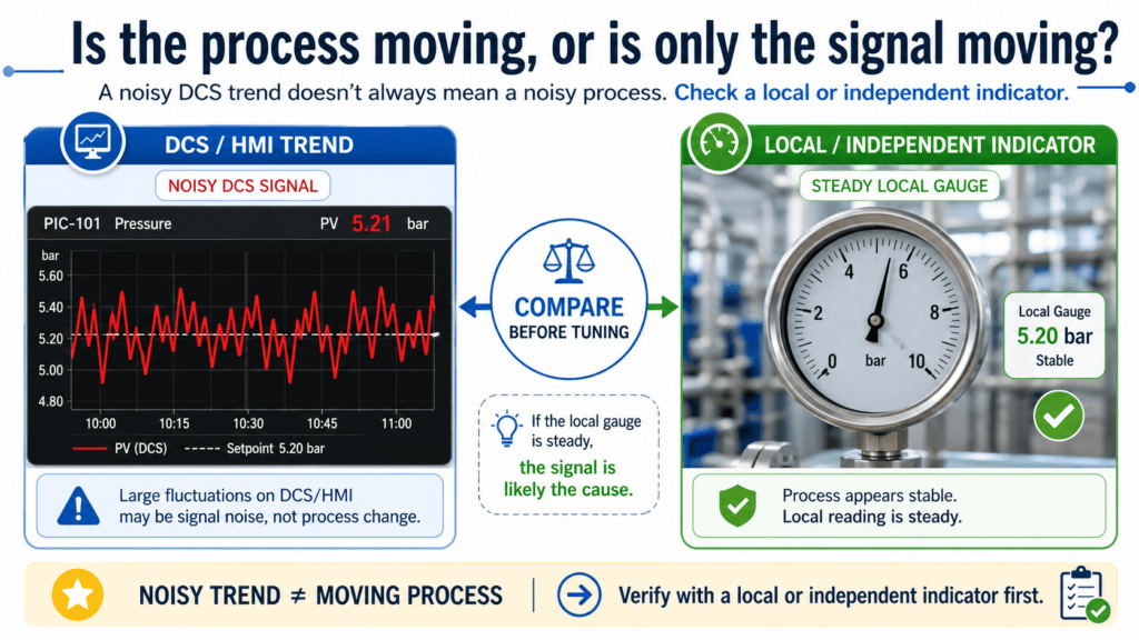
Is the process actually moving, or is only the signal moving?
That distinction changes the entire troubleshooting path.
If the process is unstable, the controller may need to respond better.
If the measurement is unstable, the controller may be reacting correctly to information that is wrong, delayed, or noisy.
Changing the PID in that condition does not solve the measurement problem.
It only changes how the controller chases it.
The Trend May Look Like a Tuning Problem
A noisy process value can make an otherwise healthy control loop look unstable.
The process value moves up.
The controller output moves down.
A moment later, the process value drops.
The controller reverses direction.
From the control-room screen, this may look like hunting caused by aggressive tuning.
But the controller may simply be following every small fluctuation it receives.
If the fluctuation is not real, the controller is moving the final control element for no useful reason.
The valve may cycle continuously.
A VFD speed reference may keep changing.
A damper actuator may move back and forth.
The equipment wears faster, while the actual process may have been relatively stable all along.
Before deciding that the PID is wrong, I want to know where the movement first appears.
The First Question: Is the Process Really Moving?
I do not begin with the PID parameters.
I begin by comparing the process value with something independent.
For pressure, that may be a local pressure gauge.
For temperature, it may be another nearby sensor or a portable reference.
For flow, it may be pump operating condition, valve position, differential pressure, or another process balance.
For level, it may be a sight glass, tank mass balance, or another level indication.
The reference does not need to be perfect.
It only needs to help answer whether the process is physically moving in the same way as the control-system signal.
For example:
- The DCS pressure value is fluctuating rapidly.
- The local pressure gauge appears steady.
- The controller output is moving continuously.
- The process equipment shows no matching disturbance.
That does not prove the transmitter is defective.
But it is enough to make me stop tuning and start checking the measurement chain.
A useful field question is:
What other evidence should move if this process fluctuation is real?
If nothing else is moving, the signal deserves closer attention.
Compare the Raw Signal with the Displayed Value
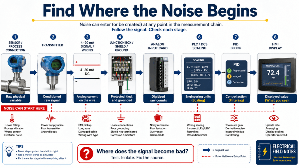
The value shown on the HMI is not always the raw field signal.
Between the sensor and the operator display, the measurement may pass through:
- Transmitter electronics
- Field wiring
- Junction boxes
- Signal isolators or barriers
- Analog input modules
- PLC or DCS scaling
- Software filtering
- Control-block filtering
- HMI trend processing
The displayed process value is the final result of that chain.
To find the problem, I try to identify where the signal first becomes unstable.
If possible, compare:
- The transmitter’s local display
- The actual 4–20 mA signal
- The analog input raw count
- The scaled engineering value
- The value entering the PID block
- The value shown on the HMI trend
The logic is simple.
If the transmitter display is stable but the DCS value is noisy, the problem is probably not the sensing element.
If the 4–20 mA signal is stable but the scaled value moves, check the input card, scaling, logic, or software processing.
If the signal is already unstable at the transmitter, move closer to the sensor, process connection, power supply, and installation.
The most useful troubleshooting question is not:
“Is the transmitter bad?”
It is:
Where does the signal become bad?
Check Range and Scaling Before Blaming Noise
Sometimes a measurement looks noisy because the configured range is too wide or too narrow for the actual process.
Consider a process normally operating between 4.9 and 5.1 bar.
If the transmitter range is 0 to 100 bar, small useful changes occupy only a very small portion of the signal range.
Resolution becomes poor.
Minor electrical noise can appear significant compared with the actual process movement.
The opposite can also happen.
If the range is too narrow, normal process changes may drive the signal close to its limits.
Before tuning, confirm:
- Transmitter lower and upper range values
- PLC or DCS scaling
- Engineering units
- Sensor resolution
- Expected operating range
- Alarm and control range
The transmitter range and the control-system scaling must agree.
A range mismatch may not only create a wrong value.
It can also change how large the apparent fluctuation looks to the controller.
Grounding and Shielding Can Make a Stable Process Look Unstable
Instrumentation noise is often treated as a software problem because that is where it becomes visible.
But the source may be physical.
Common clues include:
- Fluctuation begins after a nearby VFD starts
- Noise increases when a large motor runs
- Spikes appear during switching
- The problem began after cable work
- The signal changes when a junction box is opened or touched
- Several nearby analog signals fluctuate together
When I see those patterns, I check:
- Shield termination
- Grounding point
- Ground loops
- Cable routing
- Separation from power and VFD output cables
- Loose terminals
- Moisture or corrosion in junction boxes
- Signal isolator condition
- 24 VDC power quality
A controller cannot distinguish electrical interference from a real process change.
It receives a number and responds to it.
That is why good signal wiring is part of good control performance.
Be Careful with Filtering
Filtering is tempting because it produces an immediate visual improvement.
The trend becomes smoother.
The valve moves less.
The operator feels that the loop has become stable.
But filtering has a cost.
It adds delay.
The controller sees an older version of the process.
If too much filtering is added, the real process may begin changing while the controller is still reacting to the previous condition.
The sequence can become:
- The process starts moving.
- The filtered value changes slowly.
- The controller continues applying the previous correction.
- The process overshoots.
- The delayed measurement finally catches up.
- The controller reverses too late.
The loop may then appear poorly tuned.
The natural response is to make the PID even slower.
Now the system has both heavy filtering and slow control.
The trend may look calm, but the process response may become weak and delayed.
Before adding more filtering, check where filtering already exists.
It may be configured in:
- The transmitter damping setting
- The analog input module
- PLC logic
- The DCS input block
- The PID measurement filter
- The HMI trend display
Several small filters can create one large delay.
I prefer to solve avoidable noise at its source before hiding it with software.
Sensor Location Can Create Real but Misleading Movement
Not every unstable measurement is electrical noise.
Sometimes the sensor is accurately measuring a local disturbance that does not represent the process we want to control.
Examples include:
- A temperature sensor installed too close to a mixing point
- A pressure transmitter connected near a pulsating pump
- A flow meter installed without enough straight pipe
- A level measurement affected by agitation or foam
- A pressure tap exposed to turbulence
- A sensor installed where stratification occurs
The signal may be real.
But it may be measuring the wrong part of the process.
This is an important distinction.
Calibration will not fix poor sensor location.
Filtering may hide the movement, but it will not make the measurement more representative.
Before changing the PID, ask:
- Is the sensor installed where the process is representative?
- Is the measurement affected by pulsation, turbulence, vibration, foam, or mixing?
- Did the problem begin after piping or equipment modification?
- Has the normal operating range changed?
A technically correct measurement can still be a poor control measurement.
The Controller Output Provides a Clue
I always review the process value and controller output together.
If the process value is noisy but the controller output barely moves, the loop may already be filtered or relatively insensitive.
If both the process value and output move rapidly, the controller may be chasing the measurement.
If the output moves but the process equipment does not respond, the final control element also needs investigation.
If the output reaches its limits, the problem may be larger than signal noise.
The relationship matters more than any one trend.
At minimum, trend:
- Setpoint
- Process value
- Controller output
When available, add:
- Raw analog input
- Valve-position feedback
- Related process variables
- Equipment status
Do not look only at the shape of the process-value line.
Look at the sequence of cause and response.
What I Check Before Changing the PID
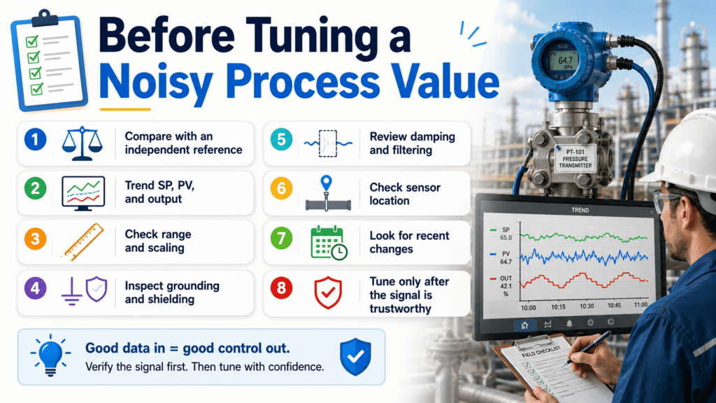
When a process value looks noisy, I use this short field sequence.
1. Confirm Whether the Process Is Moving
Compare the signal with an independent indication and related process conditions.
Ask what else should change if the movement is real.
2. Find Where the Noise Begins
Compare the transmitter display, 4–20 mA signal, raw input, scaled value, and PID input.
Do not replace parts before locating the unstable section.
3. Verify Range and Scaling
Check transmitter range, DCS scaling, engineering units, and normal operating range.
4. Inspect Wiring, Grounding, and Shielding
Look for cable routing problems, ground loops, loose terminals, moisture, and interference from nearby equipment.
5. Review Damping and Filtering
Identify every place where filtering is applied.
Do not add another filter until the total delay is understood.
6. Check Sensor Installation
Review sensor location, process connection, vibration, turbulence, pulsation, and installation changes.
7. Tune Only After the Measurement Is Trustworthy
Once the signal represents the process accurately and with acceptable delay, PID tuning becomes meaningful.
What Not to Do
There are three shortcuts I try to avoid.
Do Not Slow the PID Only to Hide the Noise
A slower controller may reduce valve movement, but the measurement problem remains.
Do Not Add Filtering at Every Layer
A smooth trend can become a delayed trend.
Too much delay creates a different control problem.
Do Not Replace the Transmitter Without Locating the Noise
The same noisy signal may return with the new transmitter if the problem is in the wiring, grounding, power supply, scaling, or installation.
Fast action is useful only when it moves the diagnosis forward.
When PID Tuning May Be Necessary
After the measurement chain is verified, the PID may still need adjustment.
The loop may be too sensitive to small but real process changes.
The original tuning may have been selected for a different operating range.
The process equipment may have changed.
The sensor response may be faster after replacement.
At that point, tuning has a clear basis.
But I would rather tune a loop using a trustworthy measurement than use tuning to compensate for a signal I do not trust.
Field Checklist: Before Tuning a Noisy Process Value
- Compare the process value with an independent reference
- Trend SP, PV, and controller output together
- Check the transmitter’s local indication
- Measure or review the raw input signal
- Confirm transmitter range and DCS scaling
- Inspect power, wiring, shield, and grounding
- Check for nearby VFD or motor interference
- Review every damping and filtering setting
- Inspect the process connection and sensor location
- Check what changed recently
- Tune only after the signal is trustworthy
Final Thought
A noisy process value can make a healthy controller look badly tuned.
The controller may not be creating the instability.
It may simply be reacting to a measurement that does not represent the process correctly.
Before changing the gain or integral time, determine whether the process is moving or only the signal is moving.
Find where the noise begins.
Check the wiring.
Check the scaling.
Check the filtering.
Check the installation.
Because good PID tuning cannot stabilize a measurement that cannot be trusted.