
A Field Checklist for E&I Engineers
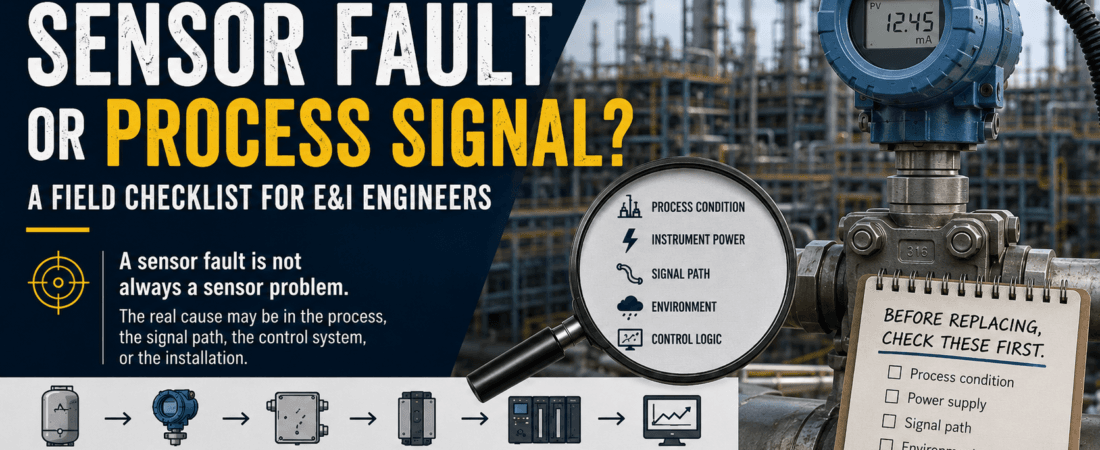
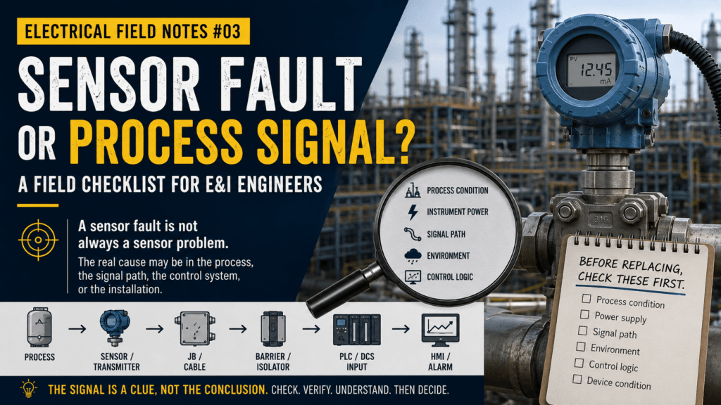
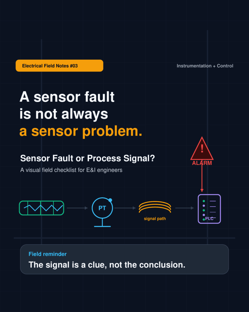
A sensor fault is not always a sensor problem.
When a transmitter alarm appears in the control room, the field device is often blamed first. It is a natural reaction. The alarm name usually points to the instrument tag, and the fastest visible action is to check, calibrate, or replace the transmitter.
But in real plant troubleshooting, the field device is only one part of the story.
A bad reading can come from a good instrument.
A healthy transmitter can still show an abnormal signal.
A process change can look like an instrument failure.
A grounding or cable issue can look like a sensor fault.
A PLC or DCS scaling issue can make the control room value different from the real field condition.
That is why I try to slow down before replacing the device.
This field note is a practical checklist for E&I engineers, maintenance engineers, and plant troubleshooting teams. It is not a textbook. It is simply a structured way to separate sensor failure, signal path problems, control system issues, and real process conditions.
1. Start with the field question
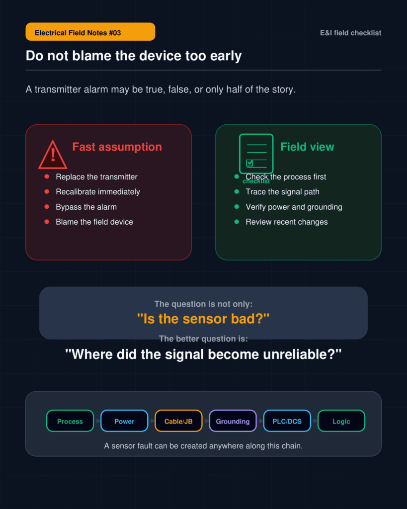
When a sensor alarm appears, the first question should not be:
“Is the transmitter bad?”
A better first question is:
“What is the signal trying to tell us?”
The signal may be telling us that the process has changed. It may be telling us that power is unstable. It may be telling us that the signal path is interrupted. It may be telling us that the control system configuration is wrong. Or it may truly be telling us that the field device has failed.
The key is not to jump directly to replacement.
In the field, a fast assumption can create three problems.
First, it can waste time and parts.
Second, it can hide the real root cause.
Third, it can allow the same fault to return later.
A transmitter replacement may clear the alarm temporarily, but if the real issue is cable noise, impulse line blockage, wrong scaling, or process instability, the problem will come back.
2. A practical signal path view
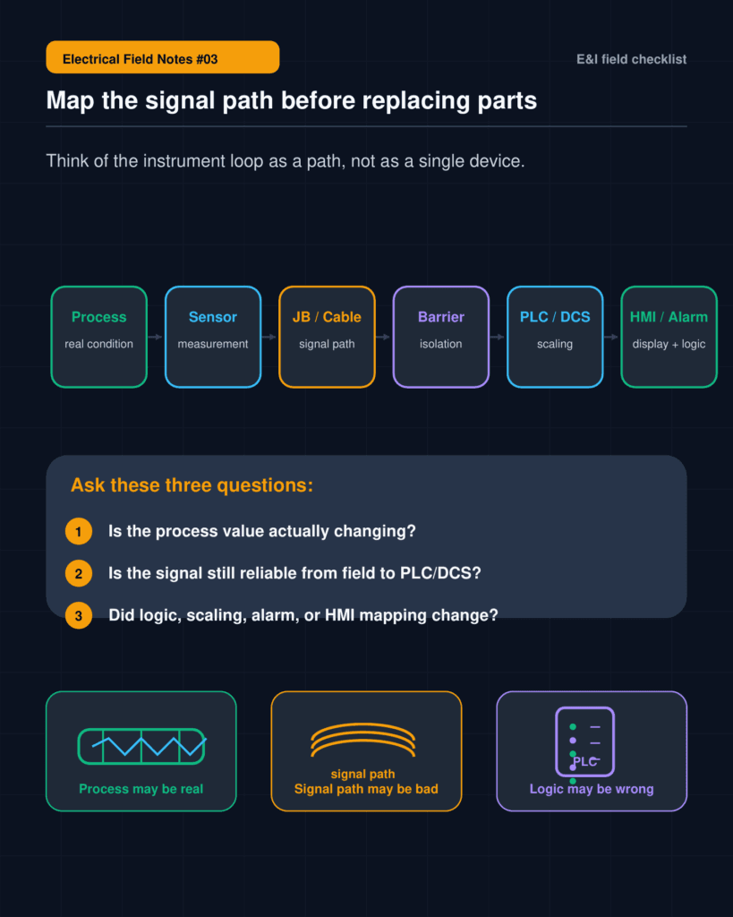
A field signal usually passes through several layers before it becomes an alarm on the screen.
A simplified signal path looks like this:
Process condition
→ Field sensor / transmitter
→ Cable and junction box
→ Barrier or isolator
→ PLC / DCS input
→ Scaling and logic
→ HMI value or alarm
If we only check the transmitter, we are checking only one part of the chain.
For example, a pressure transmitter alarm may be caused by the transmitter itself. But it may also be caused by blocked impulse tubing, a closed root valve, trapped air, damaged cable, loose terminal, signal isolator failure, wrong analog input scaling, poor shielding, or a real process pressure change.
A temperature signal may fluctuate because the sensor is damaged. But it may also fluctuate because of poor terminal contact, electrical noise, vibration, cable routing, grounding, or input card issues.
A level signal may be unstable because the device is faulty. But it may also be affected by foam, turbulence, density change, process condition, installation issue, or wrong damping setting.
The alarm name is only the starting point.
The signal path gives the troubleshooting map.
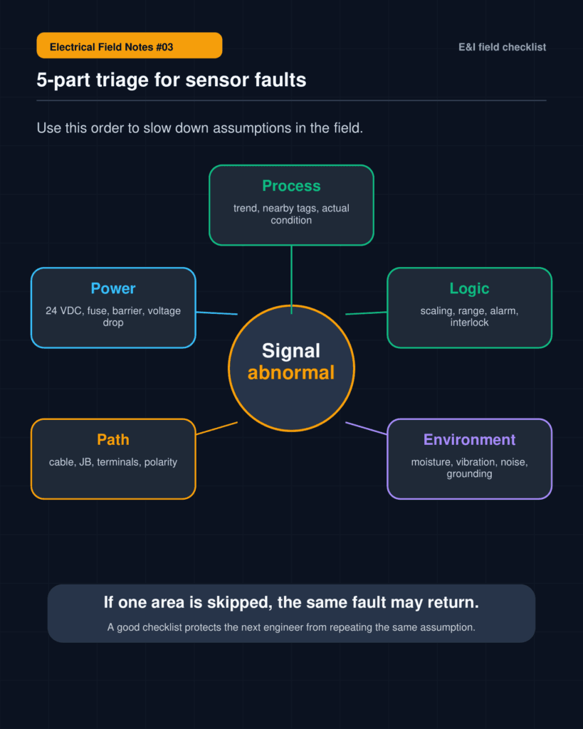
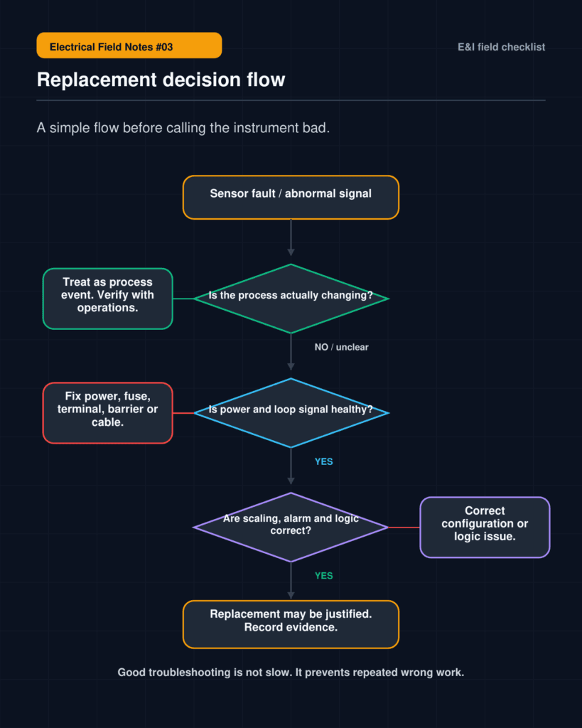
3. The 5-part triage I use before blaming the sensor
When I see a sensor fault, I like to separate the investigation into five areas.
1) Process
Is the process condition actually changing?
This should be checked early. Sometimes the instrument is not wrong. The process is simply moving faster than expected, or the operating condition has changed.
Useful checks:
- Compare with nearby related instruments.
- Review the trend before and after the alarm.
- Ask operators what changed recently.
- Check whether the plant was starting up, shutting down, switching lines, cleaning, or changing load.
- Confirm local field indication if available.
2) Power
Is the instrument power healthy?
Many transmitter issues are not transmitter issues. They are power supply or loop power issues.
Useful checks:
- Check 24 VDC supply.
- Check fuse, MCB, barrier, or isolator.
- Measure voltage at the field side if possible.
- Look for voltage drop, loose terminal, or intermittent contact.
- Check whether other instruments using the same power source are also affected.
3) Signal path
Is the signal path intact from field to control system?
The field device may be healthy, but the signal may not reach the control system correctly.
Useful checks:
- Inspect terminals at the transmitter, junction box, marshalling cabinet, and PLC / DCS panel.
- Check cable continuity and polarity.
- Confirm analog input channel assignment.
- Verify signal type: 4-20 mA, pulse, RTD, thermocouple, HART, or digital input.
- Check isolator, barrier, or signal converter.
- Compare measured loop current with the control room value.
4) Environment
Is the installation environment affecting the signal?
Instrumentation problems are often influenced by installation and environment.
Useful checks:
- Check moisture ingress.
- Inspect cable glands and enclosure sealing.
- Look for vibration or mechanical stress.
- Check cable routing near power cables or VFD output cables.
- Review shielding and grounding practice.
- Look for damaged insulation, poor termination, or corrosion.
5) Logic
Is the control system interpreting the signal correctly?
Sometimes the field signal is correct, but the control system interpretation is wrong.
Useful checks:
- Confirm PLC / DCS scaling.
- Check engineering units.
- Review alarm setpoint, deadband, and filtering.
- Check whether logic uses raw value, scaled value, or calculated value.
- Review recent logic changes.
- Check HMI mapping and tag assignment.
- Review first-up alarm sequence if a trip occurred.
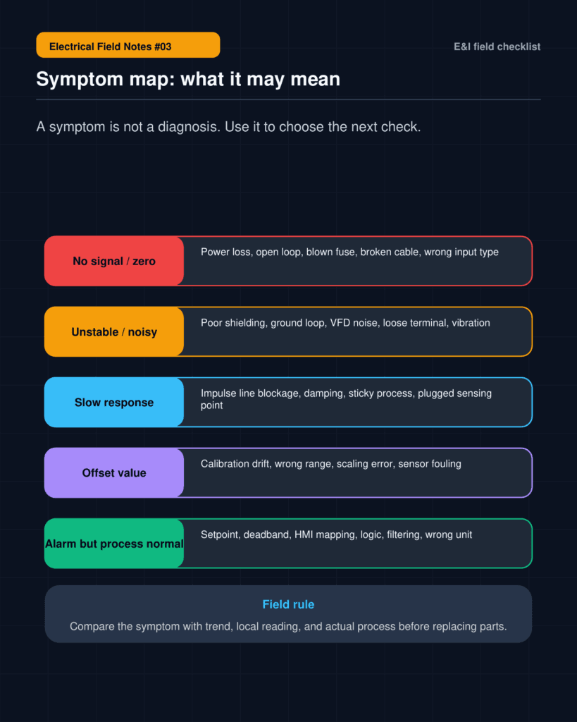
4. Symptom-based troubleshooting
A useful way to start troubleshooting is to classify the symptom.
No signal or flat zero
Possible causes:
- Loss of instrument power
- Open circuit
- Blown fuse
- Barrier or isolator failure
- Broken cable
- Wrong input type
- Disconnected terminal
- Field device failure
Unstable or noisy reading
Possible causes:
- Loose terminal
- Poor shielding
- Ground loop
- Cable routing near noise sources
- VFD-related electrical noise
- Vibration
- Moisture ingress
- Input card issue
- Process turbulence
Slow response
Possible causes:
- Blocked impulse line
- Trapped air
- Excessive damping
- Sticky process condition
- Plugged sensing point
- Tubing issue
- Wrong installation
Constant offset
Possible causes:
- Calibration drift
- Wrong range
- Scaling error
- Wrong engineering unit
- Installation bias
- Process density or temperature effect
- HMI mapping issue
Alarm but process seems normal
Possible causes:
- Wrong alarm setpoint
- Deadband issue
- Filtering issue
- Wrong PLC / DCS logic
- First-up alarm misinterpretation
- HMI display issue
- Interlock condition from another signal
This symptom-based view helps avoid one of the most common mistakes in field troubleshooting: treating every alarm as a device failure.
5. When replacement is justified
Of course, sometimes the sensor really is faulty.
A field device replacement may be justified when several checks support the same conclusion.
For example:
- Process condition is verified as normal.
- Power supply is healthy.
- Signal path is confirmed.
- Cable and terminals are checked.
- Grounding and shielding are not the suspected cause.
- PLC / DCS scaling and logic are verified.
- Local measurement and control room value do not match due to device output.
- Device configuration, calibration, or physical condition shows abnormal behavior.
The important point is not to avoid replacement. The point is to make replacement a conclusion, not an assumption.
A good troubleshooting process should leave a trace.
What was observed?
What was checked?
What was ruled out?
Why was replacement selected?
What should be monitored after replacement?
That trace becomes useful for the next engineer.
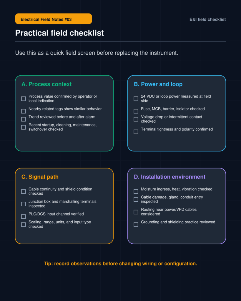
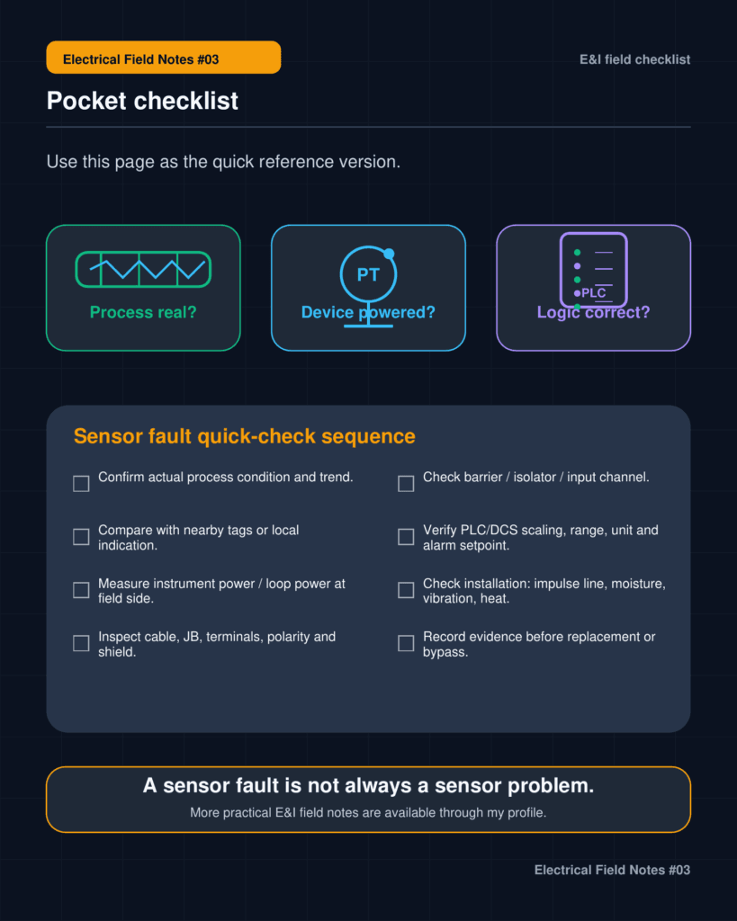
6. A simple field checklist
Before replacing a sensor or transmitter, I would check these items first.
Process and operation
- Did the process condition really change?
- Are nearby related tags showing similar movement?
- Did startup, shutdown, cleaning, switching, or maintenance happen recently?
- Is there a local gauge or independent indication to compare?
Instrument power
- Is 24 VDC available at the field side?
- Are fuses, MCBs, barriers, and isolators healthy?
- Is there voltage drop or intermittent power loss?
- Are other instruments on the same power source affected?
Signal path
- Are terminals tight at the field device, junction box, and panel?
- Is polarity correct?
- Is cable continuity confirmed?
- Is the correct input channel assigned?
- Does measured loop current match the control room value?
Installation and environment
- Is there moisture, vibration, heat, or corrosion?
- Is the cable gland or enclosure sealing damaged?
- Is the signal cable routed near power or VFD cables?
- Is shielding and grounding applied correctly?
- Is there any sign of physical cable damage?
Device-side condition
- Is the impulse line blocked or isolated?
- Are valves in the correct position?
- Is there trapped air or plugged tubing?
- Is the device range correct?
- Is damping or configuration appropriate?
- Is calibration history reasonable?
PLC / DCS / HMI
- Is scaling correct?
- Are units and range correct?
- Is the alarm setpoint correct?
- Is deadband or filtering appropriate?
- Was there a recent logic change?
- Is the HMI tag mapping correct?
- Is the alarm a first-up cause or a consequence?
7. Field lesson
The field device is often blamed first.
Sometimes it deserves it.
Sometimes it does not.
A sensor fault can be a real device failure. But it can also be a process signal, a wiring problem, a grounding problem, a power supply issue, a configuration issue, or a control logic problem.
The signal is a clue, not the conclusion.
That small shift in thinking can save time, reduce unnecessary replacement, and lead to better root cause analysis.
This is the reason I keep making these field notes.
Not as a textbook.
Not as a perfect standard.
Just as a practical way to organize what the field keeps teaching.